Cl
N/O
POINT
Figure
30.
10
BOUNCING
Cl
N/O
POINT
Figure
30.
I I
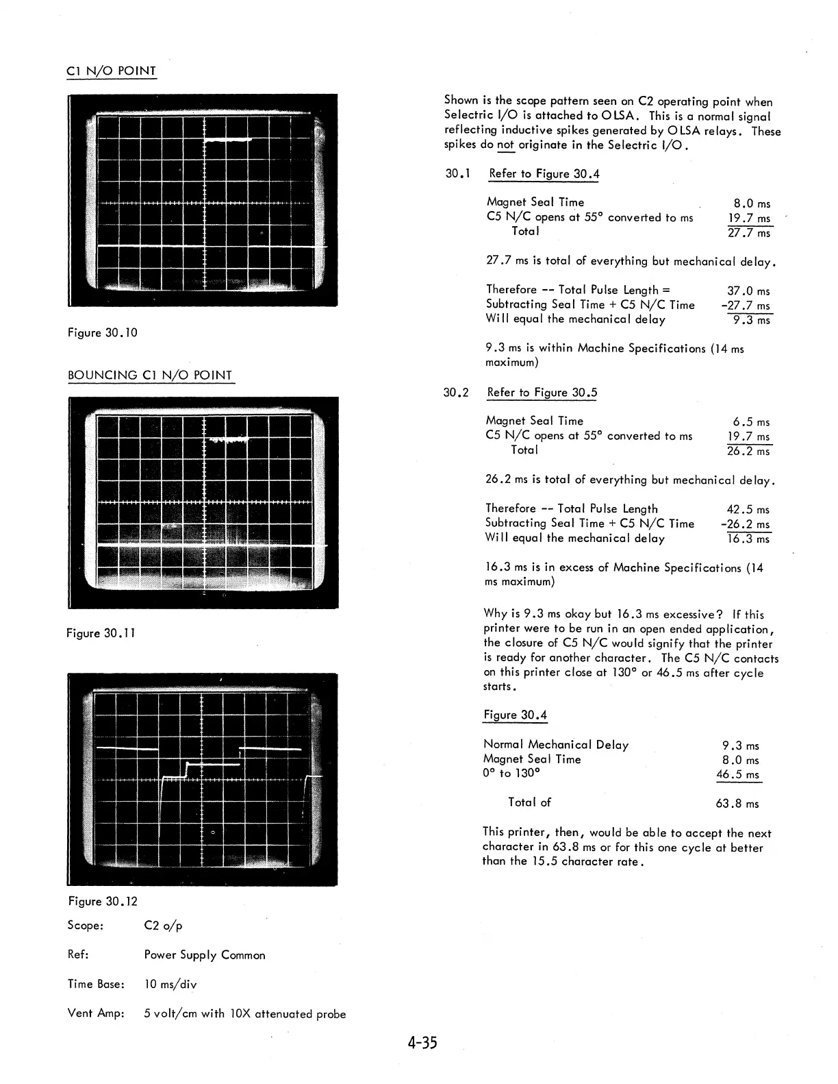
Figure
30.12
Scope: C2
o/p
Ref:
Power Supply Common
Time
Base:
10
ms/div
Vent
Amp:
5
volt/cm
with
lOX
attenuated
probe
4-35
Shown
is
the scope pattern seen
on
C2 operating point when
Selectric
I/O
is
attached
to
OLSA.
This
is
a normal signal
reflecting inductive spikes
generated
by 0
LSA
relays.
These
spikes do not originate in the
Selectric
I/O.
30.1
Refer to Figure
30.4
Magnet Seal Time
C5
N/C
opens
~t
55° converted to
ms
Total
8.0
ms
19.7
ms
27.7
ms
27.7
ms
is
total of everything but mechanical
delay.
Therefore
--
T
ota
I
Pu
Ise
Length =
Subtracting Seal
Time
+ C5
N/C
Time
Will equal
the
mechanical
delay
37.0
ms
-27.7
ms
9.3
ms
9.3
ms
is
within Machine Specifications (14
ms
maximum)
30.2
Refer to Figure
30.5
Magnet Seal Time
C5
N/C
opens
at
55°
converted
to
ms
Total
6.5
ms
19.7
ms
26.2
ms
26.2
ms
is
total
of everything but mechanical
delay.
Therefore
--
Total Pulse Length
Subtracting
Seal Time + C5
N/C
Time
Will equal
the
mechanical
delay
42.5
ms
-26.2ms
16.3
ms
16.3
ms
is
in excess of Machine Specifications (14
ms
maximum)
Why
is
9.3
ms
okay but
16.3
ms
excessive?
If
this
pri nter were
to
be
run
in an open ended app
Ii
cati
on,
the closure of C5
N/C
would signify
that
the
printer
is
ready for another
character.
The C5
N/C
contacts
on
this printer close
at
130° or
46.5
ms
after
cycle
starts.
Figure
30.4
Normal Mechanical Delay
Magnet Seal Time
0°
to
130
0
Total of
9.3
ms
8.0
ms
46.5
ms
63.8
ms
This
printer,
then,
would be
able
to
accept
the next
character
in
63.8
ms
or for this one
cycle
at
better
than the
15.5
character
rate.
 Loading...


