3.
Armature Stop - With
the
armature manually
attracted,
adjust for a
clearance
of
.004"
to
.008"
between
the
armatures and yokes (Fig. 12 - see Fig. 11 for assembly
end view)
• Measure
clearances
at
the outside
arma-
tures
(T2
& R5).
Armature
Mtg.
Bracket
'-..c,r-=
___
~~
Gu;d,
Armature Stop Stop Screw
FIGURE
11.
Armature Stop
4.
Armature
Guide
- Position horizontally so that the
arm-
atures
are
centered
in the guide slotS (Fig. 11).
.004"
to
.008"
Armature
Armature Stop
FIGURE
12.
Armature Stop
5.
Back Stop (Fig. 13) - Position
vertically
(with
arma-
tures
at
rest) for a
clearance
of
.041"
to
.044"
between
the
armature stop
and
armatures. Measure
clearance
at
the
outside armatures
(T2
& R5).
Armature
I~"'
__
Mtg.
Screw
.041"
-
Armature Stop
FIGURE
13.
Armature Backstop
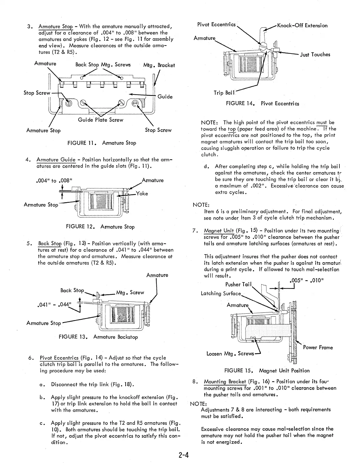
6.
Pivot Eccentrics (Fig.
14)-
Adjust so
that
the
cycle
clutch
trip
bail
is
parallel
to
the armatures.
The
follow-
ing procedure may be used:
a.
Disconnect
the
trip
link (Fig. 18).
b.
Apply slight pressure
to
the knockoff extension (Fig.
17)or
trip link extension
to
hold
the
bail in
contact
with
the
armatures.
c.
Apply slight pressure to
the
T2
and
R5
armatures (Fig.
10).
Both
armatures should be touching
the
trip
bail.
If
not,
adjust
the
pivot eccentrics
to
satisfy this
con-
dition.
2-4
Arm
581~~~~~fr"'''''''~---
Just Touches
FIGURE
14.
Pivot Eccentrics
NOTE: The high point
of
the
pivot
eccentrics
must be
toward
the
top
(paper feed area)
of
the machine
~
the
pivot
eccentrics
are. not positioned to the
top,
the
print
magnet armatures will
contact
the
trip
bail too soon,
causing sluggish operation or failure to
trip
the
cycle
clutch.
d.
After completing step
c,
while holding the trip bail
against
the
armatures,
check
the center. armatures
tr
be sure
they
are touching
the
trip
ban
or
clear
it
b},
a maximum of
.002".
ExcessiveVclearance can cause
extra
cycles.
NOTE:
Item
6
isa
preliminary adjustment.
For
final adjustment,
see note
unde~
Item 3 of
cycle
clutch trip mechanism.
7.
Magnet Unit
(Fig.
15) - Position under its two mounting (
screws for
.005"
to
.010"
clearance
between the
pusher·
tai
Is
and armature latching surfaces (armatures
at
rest).
This
adjustment insures
that
the
pusher does not
contact
its latch extension when the pusher
is
against its armatur'.
during a print
cycle.
If
allowed to touch
mal-selection
wi
II
resu
It.
Pusher Tail
-Ij-J05"
-
.010"
Latching
surface~.
II
Armature •
'- .
. Power Frame
FIGURE
15~
Magnet Unit Position
8.
Mounting Bracket (Fig.
16).-
Position under its
fou'
mounting screws for
.001"
to
.010"
clearance
between
the
pusher tai
Is
and
armatures.
NOTE:
Adjustments 7
& 8
are
interacting - both requirements
must be
satisfied.
Excessive
clearance
may cause mal-selection since the
armature may not hold
the
pusher tai I when the magnet
is
not
energized.