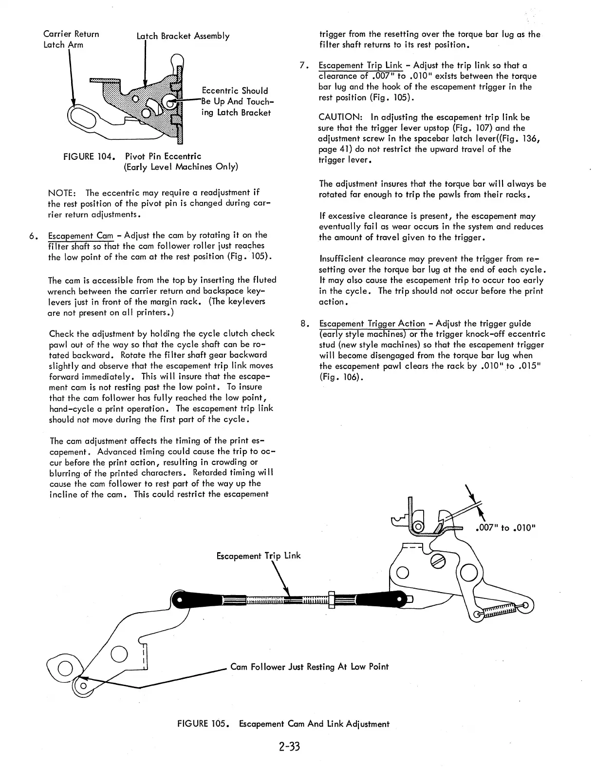
Carrier Return
Latch
Arm
Bracket Assembly
Eccentric Should
.-.l:=;'--I~",
Up
And T
ouch-
ing Latch Bracket
FIGURE
104.
Pivot Pin Eccentric
(Early Level Machines
Only)
NOTE:
The
eccentric
may require a readjustment
if
the
rest position of the pivot pin is changed during
car-
ri
er
return adj ustments •
6.
Escapement
Cam
- Adjust
the
cam by rotating
it
on
the
filter
shaft so
that
the cam follower roller just reaches
the
low point of
the
cam
at
the rest position (Fig. ·105).
The
cam
is
accessible
from
the top by inserting the fluted
wrench between
the
carrier
return and backspace
key-
levers just in front
of
the
margin
rack.
(The
keylevers
are
not present on
all
printers.)
Check the adjustment by holding
the
cycle
clutch
check
pawl out of
the
way so
that
the
cycle
shaft can be
ro-
tated
backward. Rotate
the
filter
shaft
gear
backward
slightly and observe
that
the
escapement
trip
link moves
forward immediately.
This
will insure that the
escape-
ment cam
is
not resting past
the
low
point.
To
insure
that
the
cam follower has fully reached
the
low
point,
hand-cycle
a print
operation.
The
escapement trip link
should not move during the first part of
the
cycle.
The
cam adjustment affects the timing of
the
print
es-
capement.
Advanced timing
could
cause
the
trip
to
oc-
cur before
the
print
action,
resulting in crowding or
blurring of the printed
characters.
Retarded timing will
cause the cam follower to rest part of the way up the
incline
of
the
cam.
This could restrict
the
escapement
trigger
from
the resetting over the torque
bar
lug as
the
fi
Iter shaft returns to its rest position.
7.
Escapement Trip Link - Adjust
the
trip link so
that
a
clearance
of
.007"
to
.010"
exists between the torque
bar lug and
the
hook
of
the
escapement trigger in
the
rest position (Fig. 105) .
CAUTION:
In
adjusting the escapement trip link be
sure
that
the trigger lever upstop (Fig. 107) and the
adjustment screw in
the
spacebar
latch
lever«Fig.
136,
page 41) do not restrict the upward travel
of
the
trigger
lever.
The
adjustment insures
that
the
torque bar will always be
rotated far enough
to
trip
the pawls
from
their
racks.
If
excessive
clearance
is
present,
the
escapement may
eventually
fai I as
wear
occurs in
the
system
and
reduces
the
amount of travel
given
to
the
trigger.
Insufficient
clearance
may prevent
the
trigger
from
re-
setting over the torque bar lug
at
the end of
each
cyc
Ie.
It
may also cause
the
escapement
trip
to
occur
too
early
in
the
cycle.
The
trip
should not
occur
before
the
print
action.
8.
Escapement Trigger Action - Adjust
the
trigger guide
(early style machines) or
the
trigger knock-off
eccentric
stud (new style machi nes) so
that
the
escapement
trigger
wi
II
become disengaged
from
the
torque bar lug when
the
escapement pawl clears
the
rack by
.010"
to
.015"
(Fig. 106).
Cam Follower Just Resting At
Low
Point
FIGURE
105.
Escapement Cam And Link Adjustment
2-33
 Loading...


