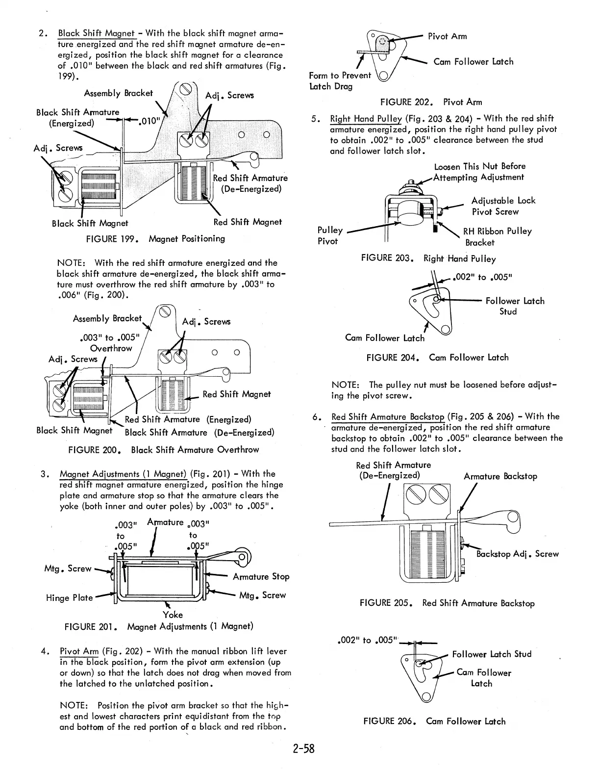
2.
Black Shift
Magnet
- With
the
black
shift magnet
arma-
tureenergized
and
the
red shift magnet armature
de-en-
ergized,
position
the
black
shift magnet for a
clearance
of
.0lD" between
the
black
and
red shift armatures
(Fig.
199).
rRed Shift
Armatur~
~==~JJ
(De-Energized)
Black
Shift Magnet
Red
Shift Magnet
FIGURE
199.
Magnet
Positioning
NOTE: With
the
red shift armature
energized
and
the
black
shift armature
de-energized,
the
black
shift
arma-
ture
must overthrow
the
red shift armature by .003"
to
.006"
(Fig.
200).
Assembly Bracket
.003"
to
.005"
Overthrow
Adj.
Screws
o 0
(Energized)
Black
Shift Armature (De-Energized)
FIGURE 200. Black Shift Armature
Overthrow
3.
Magnet Adjustments
(1
Magnet) (Fig. 201) - With
the
red shift magnet armature
energized,
position
the
hinge
plate
and armature stop so
that
the
armature
clears
the
yoke (both
inner
and
outer
poles) by .003"
to
.005".
't~03n
A/rmature
=t~03"
.005"
Mtg.
Screw
Hinge
Plate
Yoke
FIGURE 201. Magnet Adjustments
(1
Magnet)
4.
Pivot
Arm
(Fig.
202) - With
the
manual ribbon lift
lever
in
the
black
position,
form
the
pivot arm extension (up
or down) so
that
the
latch
does not drag when moved
from
the
latched
to
the
unlatched
position.
NOTE: Position
the
pivot arm
bracket
so
that
the
high-
est
and
lowest
characters
print equi distant
from
the
top
and
bottom
of
the
red portion
o~
a
black
and red
ribbon.
Pivot Arm
Cam Follower Latch
FIGURE 202. Pivot Arm
5.
Right Hand Pulley
(Fig.
203 & 204) - With
the
red shift
armature
energized,
position
the
right hand
pulley
pivot
to
obtain .002"
to
.005"
clearance
between
the
stud
and follower
latch
slot.
Pulley
Pivot
Loosen This
Nut
Before
Attempting Adjustment
Adjustable
lock
Pivot Screw
.~
RH
Ribbon Pulley
Bracket
FIGURE
203. Right Hand Pulley
.002"
to
.005"
C».04--_
Follower Latch
Stud
Cam Follower Latch
FIGURE
204. Cam Follower Latch
NOTE: The
pulley
nut
must
be
loosened before
adjust-
ing
the
pivot
screw.
6.
Red
Shift Armature Backstop
(Fig.
205 & 206) - With
the
armature
de-energized,
position
the
red shift armature
backstop
to
obtain
.002"
to
.005"
clearance
between
the
stud and
the
follower
latch
slot.
2-58
Red
Shift Armature
(De-Energized)
Armature Backstop
..---=~~~
FIGURE
205.
Red
Shift Armature Backstop
.002"
to
.005"'--1--1
...
_-
Follower Latch Stud
Cam Follower
Latch
FIGURE
206. Cam Follower Latch