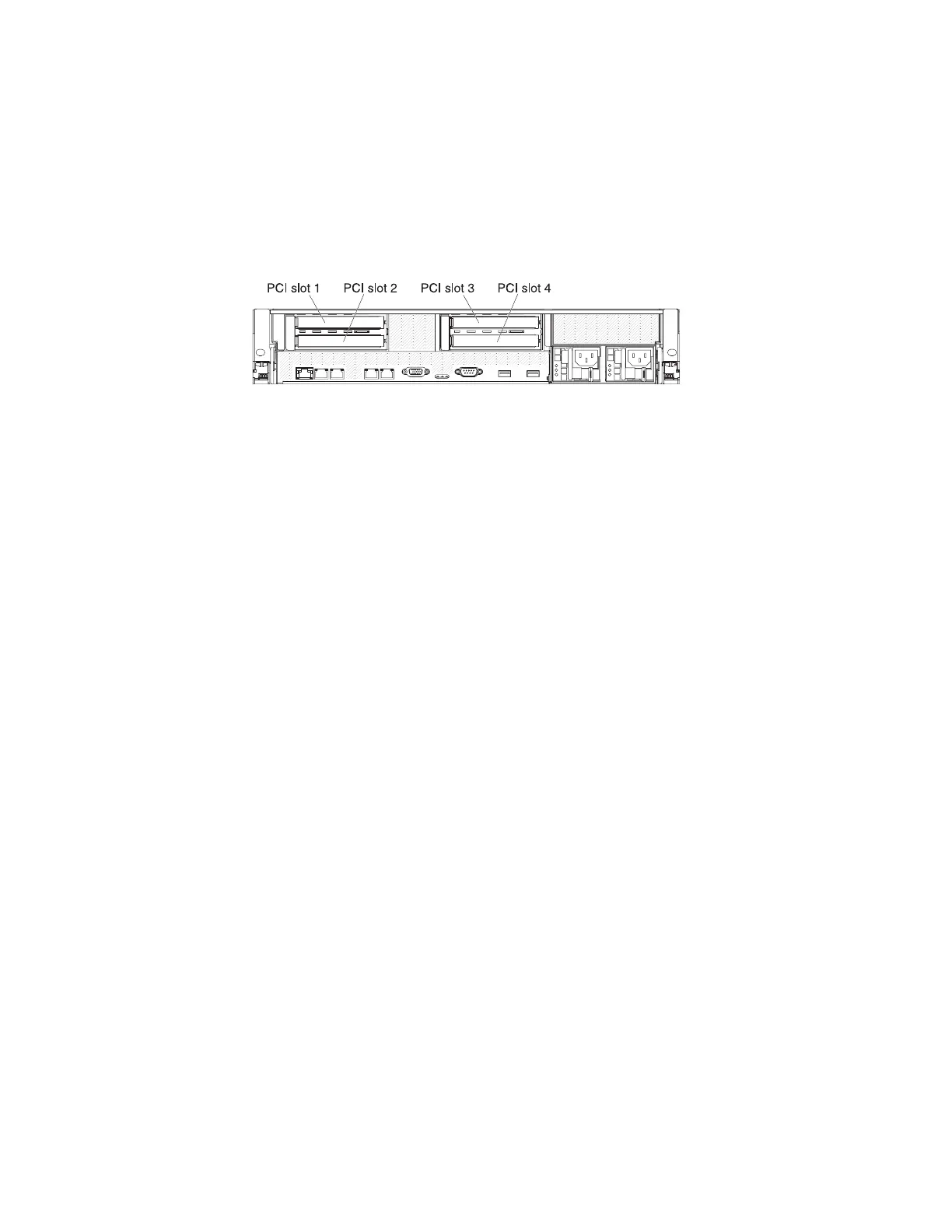
Installing a 10-Gbps Ethernet PCI adapter
These installation instructions show the slot location for the 10-Gbps Ethernet PCI
adapter.
The 10-Gbps Ethernet adapter must go in PCI slot 4.
The following illustration shows the locations of the adapter expansion slots from
the rear of the file module.
Refer to “Installing a PCI adapter in a PCI riser-card assembly” on page 103 for
instructions.
Removing the two-port Ethernet adapter
The following procedure is for a Tier 1 customer replaceable unit (CRU).
Replacement of Tier 1 CRUs is your responsibility. If IBM installs a Tier 1 CRU at
your request, you will be charged for the installation. Service agreements can be
purchased so that you can ask IBM to replace these units.
Note: Before running a procedure, refer to “Removing a file module to perform a
maintenance action” on page 51.
To remove the two-port Ethernet adapter, complete the following procedure.
1. To help you work safely with Storwize V7000 Unified file modules, read the
safety information in “Safety” on page xi, “Safety statements” on page xiii, and
“Installation guidelines” on page 54.
2. Turn off the file module and peripheral devices, then label and disconnect both
power cords and all external cables.
3. Press down on the left and right side latches and pull the server out of the rack
enclosure until both slide rails lock.
4. Remove the cover, as described in “Removing the cover” on page 83.
5. Remove the PCI riser-card assembly as described in “Removing a PCI riser-card
assembly” on page 99.
6. Grasp the Ethernet adapter and disengage it from the standoffs and the
connector on the system board; then, slide the Ethernet adapter out of the port
openings on the rear of the chassis and remove it from the server. See Figure 12
on page 107.
Note: You may need to squeeze the springs on the head of the stand off with a
pair of pliers, for example, at the same time as lifting up on the adapter from a
point near the same stand-off.
106 Storwize V7000 Unified: Problem Determination Guide Version

 Loading...


