Attention:
v Do not allow the thermal grease on the microprocessor and heat sink to come in
contact with anything. Contact with any surface can compromise the thermal
grease and the microprocessor socket.
v Dropping the microprocessor during installation or removal can damage the
contacts.
v Do not touch the microprocessor contacts; handle the microprocessor by the
edges only. Contaminants on the microprocessor contacts, such as oil from your
skin, can cause connection failures between the contacts and the socket.
To remove a microprocessor and heat sink, complete the following steps:
1. To help you work safely with Storwize V7000 Unified file modules, read the
safety information in “Safety” on page xi, “Safety statements” on page xiii,
and “Installation guidelines” on page 54.
2. Turn off the server and peripheral devices, then label and disconnect both
power cords and all external cables
3. Remove the cover, as described in “Removing the cover” on page 83.
4. Depending on which microprocessor you are removing, remove the following
components, if needed:
v Microprocessor 1: PCI riser card assembly 1 and DIMM air baffle, as
described in “Removing a PCI riser-card assembly” on page 99 and
“Removing the DIMM air baffle” on page 93.
Note: If there are two microprocessors, you must remove PCI riser card
assembly 2 and microprocessor 2 air baffle first, as described in “Removing
a PCI riser-card assembly” on page 99 and “Removing the microprocessor 2
air baffle” on page 90.
v Microprocessor 2: PCI riser card assembly 2 and microprocessor 2 air baffle,
as described in “Removing a PCI riser-card assembly” on page 99 and
“Removing the microprocessor 2 air baffle” on page 90.
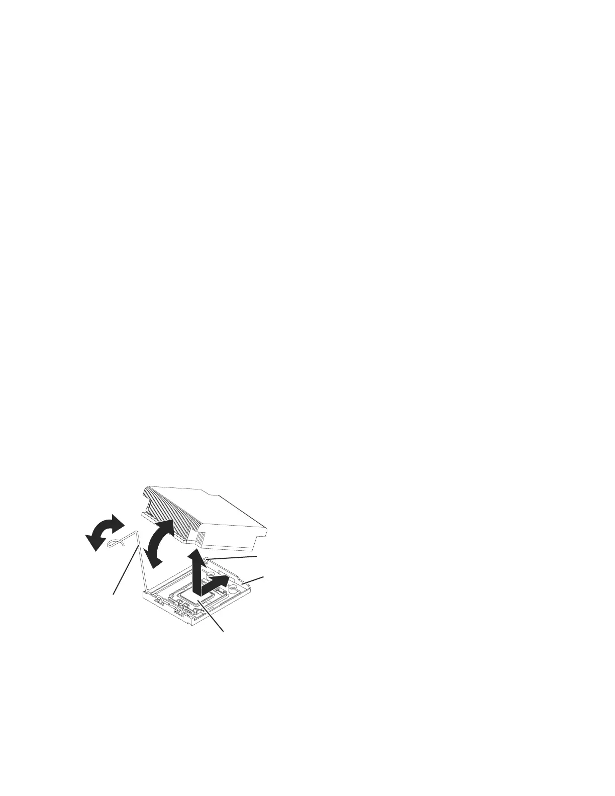
5. Open the heat-sink release lever to the fully open position. See Figure 39.
6. Lift the heat sink out of the server. If the heat sink sticks to the
microprocessor, slightly twist the heat sink back and forth to break the seal.
After removal, place the heat sink on its side on a clean, flat surface.
7. Release the microprocessor retention latch by pressing down on the end,
moving it to the side, and releasing it to the open (up) position. See Figure 40
on page 142
Retainer bracket
Microprocessor
Heat sink
release lever
Lock tab
sonas213
Figure 39. Heat-sink release lever
Chapter 4. File module 141

 Loading...


