- The following table lists the DIMM installation sequence for
memory-mirroring mode.
Table 24. Memory-mirroring mode DIMM population sequence for the memory expansion
module
Sets of 4 DIMMs DIMM connector population sequence
Set 1 9, 16, 28, 29
Set 2 1, 8, 20, 21
Set 3 11, 14, 26, 31
Set 4 3, 6, 18, 23
Set 5 10, 15, 27, 30
Set 6 2, 7, 19, 22
Set 7 12, 13, 25, 32
Set 8 4, 5, 17, 24
Note: When you populate DIMMs in the memory expansion module,
populate the larger capacity DIMMs first, then the smaller capacity DIMMs.
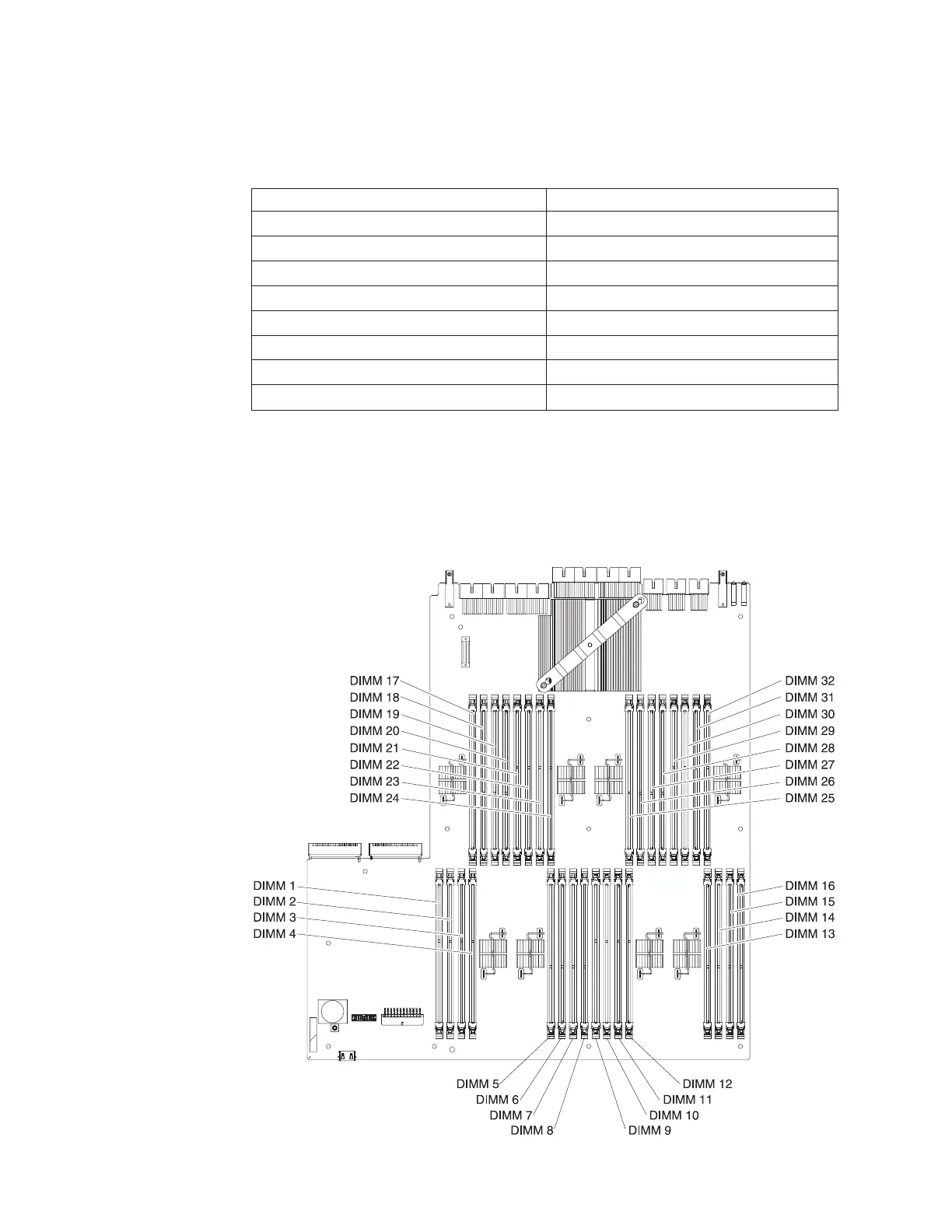
The following illustration shows the locations of the DIMM connectors on the
memory expansion module system-board tray.
190 IBM System x3850 X5 and x3950 X5 Types 7145, 7146, 7143, and 7191: Problem Determination and Service Guide
 Loading...


