16
ANTENNA TUNER OPERATION
16-3
Previous view
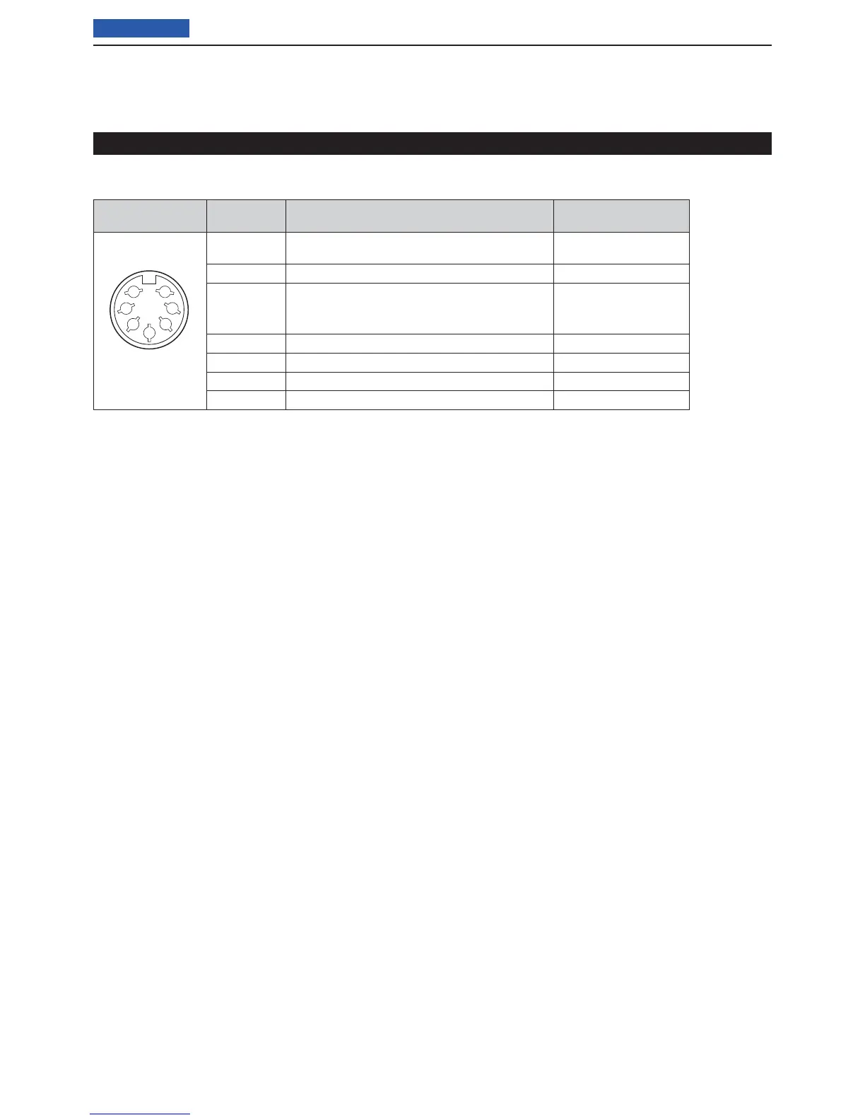
Connector information for the ACC(2) socket D
PIN LAYOUT
PIN NO./
NAME
DESCRIPTION SPECIFICATIONS
1
2
3
4
5
6
7
(Front panel view)
8 V q
Regulated 8 V output when the Band Voltage
modifi cation is performed. (p. ??-??)
Same as ACC pin q.
GND w Connects to ground.
–
HSEND e
Input/output pin.
Goes to ground when transmitting
When grounded, transmits.
Same as ACC pin e.
NC r No connection.
–
ALC t ALC output voltage
Same as ACC pin y.
NC y No connection.
–
13.8 V u
13.8 V output when power is ON
Same as ACC pin i.
Specifi cations for the AH-4 D
Frequency coverage : 7–54 MHz (with an AH-2b)
3.5–54 MHz (with more than
7 meters long wire)
Input impedance : 50 ȍ
Maximum input power : 120 W
Minimum tuning power : 10 W (5–15 W)
Tuning accuracy : Less than SWR 2:1
Power supply requirements
: 13.8 V DC/1 A (supplied from
the transceiver’s ACC socket)
Dimensions (mm/in) :
172(W) u 69.5(H) u 230(D)
6.7 (W) u 2.7(H) u 9.0(D)
Weight (Approximately) : 1.2 kg; 2.6 lb
Supplied accessories : See the AH-4 instruction
manual
Specifi cations for the AT-180 D
Frequency coverage : 1.8–54 MHz
Input impedance : 50 ȍ
Maximum input power : 120 W
Minimum tuning power : 8 W
Matching impedance range
: 16.7–150 ȍ (HF band)
20–125 ȍ (50 MHz band)
Tuning accuracy : Less than SWR 1.5:1
Insertion loss : Less than 1.0 dB
(after tuning)
Power supply requirements
: 13.8 V DC/1 A (supplied from
the transceiver’s ACC socket)
Dimensions (mm/in) :
167(W) u 58.6(H) u 225(D)
6.6(W) u 2.3(H) u 8.9(D)
Weight (Approximately) : 2.3 kg; 5.1 lb
Supplied accessories : ACC cable (DIN 13 pins)
Coaxial cable (1 m),
Connecting the antenna tuner (Continued)