16
ANTENNA TUNER OPERATION
16-6
Previous view
Operating D
The AT-180 AUTOMATIC ANTENNA TUNER automatically
matches to your antenna. Once the tuner matches the
antenna, the variable capacitor settings are memorized
as a preset point for each frequency range (100 kHz
steps). Therefore, when you change the frequency
range, the variable capacitors are automatically preset
to the memorized point.
NOTE:
• The AT-180 can match both the HF and 50 MHz
bands. However, operation is different for the
bands.
• When connecting the AT-180, the transceiver’s out-
put power should be more than 8 W. Otherwise, the
AT-180 may not tune correctly. The AT-180’s mini-
mum operating input power is 8 W.
Check the transceiver’s output power is set to 8 W/ q
Push w
(L) or [TUNER/CALL] on the re-
mote control microphone to turn ON the AT-180.
• “ ” appears.
For the HF band:
The antenna is automatically tuned during transmit if
the antenna SWR is higher than 1.5:1.
For the 50 MHz band:
“
” blinks if the antenna SWR is higher than
1.5:1, regardless of the internal switch position de-
scribed on the page ??-??. In this case, do the step
e to manually tune the antenna.
• If you continue to transmit without retuning, “ ” goes
out after approximately 10 seconds, the AH-4 is bypassed
and the antenna wire is directly connected.
Push e
(L) or [TUNER/CALL] on the re-
mote control microphone for 1 second to start man-
ual tuning.
• When the CW mode is selected, a side tone is emitted,
and “
” blinks.
NOTE: DO NOT change the frequency and oper-
ating mode while
“ ” is blinking.
r
“ ” is still ON after the tuning is completed, and
the previously selected operating mode is automati-
cally selected.
• When the connected wire cannot be tuned, “ ” goes
out, the AH-4 is bypassed and the antenna wire is di-
rectly connected.
Once the tuner matches the antenna, the variable
capacitors are automatically preset to the memo-
rized point when you change the frequency range in
100 kHz steps.
• While presetting, “ ” blinks.
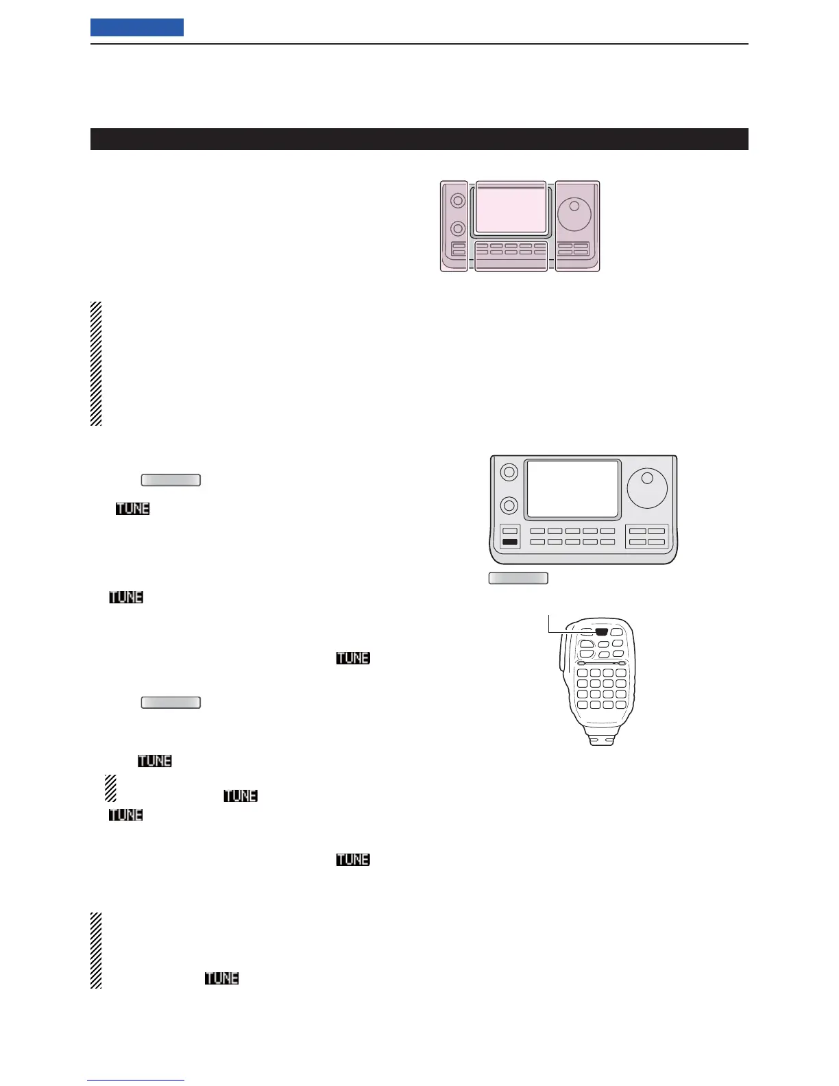
Operating the AT-180 (Continued)
[TUNER/CALL]
The L, R, C or D in the
instructions indicate the
part of the controller.
L: Left side
R: Right side
C: Center bottom
D: Display (Touch panel)
L
eft
R
ight
C
enter
D
isplay