IDEAL INDUSTRIES Inc. 2-1
2 Setup and Configuration
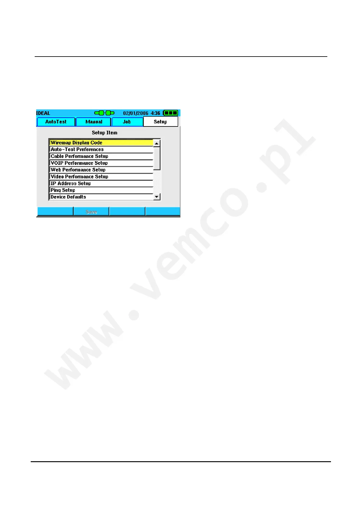
The following section describes the various options that are
available in the Setup tab.
Figure 2-1 Setup Tab
Wire map Display Color Code
The color display of the wire map can be set to one of three
options: TIA 568A, 568B, USOC or None. Changing this option
only affects the way the colors are displayed when viewing the wire
map test result. It does not affect the actual result of the wire map
test. Selecting either 568 A or B makes diagnosing wire map
problems easier because the color of the conductor is correctly
represented in the SIGNALTEK display.
Universal Service Order Code (USOC) is used when testing three-
pair cables for voice applications. In this configuration the pairing
sequence is:
Pair 1 (Blue) = Pins 4/5
Pair 2 (Orange) = Pins 3/6
Pair 3 (Green) = Pins 2/7
 Loading...