IDEAL INDUSTRIES, Inc. vi
Table of Figures
Figure 1-1 T-568 A/B Color Code................................................. 1-5
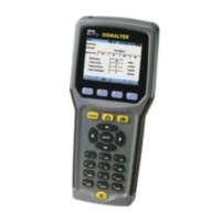
Figure 1-2 SIGNALTEK Handsets................................................ 1-9
Figure 1-3 Battery Discharge Characteristics............................. 1-13
Figure 1-4 AutoTest Tab - Active................................................1-16
Figure 1-5 AutoTest Tab - Inactive .............................................1-17
Figure 2-1 Setup Tab.................................................................... 2-1
Figure 2-2 Wire map Display Preferences ................................... 2-2
Figure 2-3 Autotest Preferences................................................... 2-2
Figure 2-4 Remote Detected ........................................................ 2-3
Figure 2-5 Active LAN (Link) Detected......................................... 2-3
Figure 2-6 No Link Detected......................................................... 2-3
Figure 2-7 Cable Performance Setup........................................... 2-5
Figure 2-8 VoIP Setup .................................................................. 2-6
Figure 2-9 IP Address Setup ........................................................ 2-7
Figure 2-10 Ping Setup................................................................. 2-8
Figure 2-11 Owner Information..................................................... 2-9
Figure 2-12 Display Contrast...................................................... 2-10
Figure 2-13 Timeout Options...................................................... 2-10
Figure 2-14 Measurement Units ................................................. 2-11
Figure 2-15 Date and Time......................................................... 2-11
Figure 2-16 Cable ID Prefix Setup.............................................. 2-12
Figure 2-17 Language Setup...................................................... 2-13
Figure 2-18 Factory Defaults ......................................................2-13
Figure 2-19 Firmware Version ....................................................2-14
Figure 3-1 Job Tab........................................................................ 3-1
Figure 3-2 USB Printer Cable....................................................... 3-4
Figure 4-1 Autotest Tab ................................................................ 4-1
Figure 5-1 Wire map Results ........................................................ 5-1
Figure 5-2 Link Establishment Results......................................... 5-3
Figure 5-3 Cable Performance Results ........................................ 5-4
Figure 6-1 SIGNALTEK-FO Top Connectors............................... 6-2
Figure 6-2 LC-to-SC cable............................................................ 6-3
Figure 6-3 SC Coupler.................................................................. 6-3
 Loading...