IDEAL INDUSTRIES, Inc. 2-10
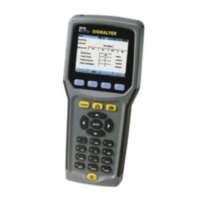
Figure 2-12 Display Contrast
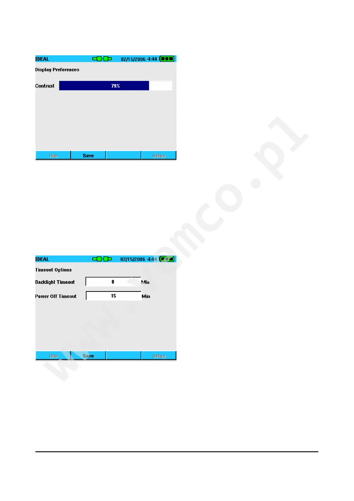
Timeout Options
The Timeout Options screen is used to set the time that the display
backlight and handset stay on during periods of inactivity. Entering
“0” prevents the display or handset for automatically turning off.
Figure 2-13 Timeout Options
 Loading...