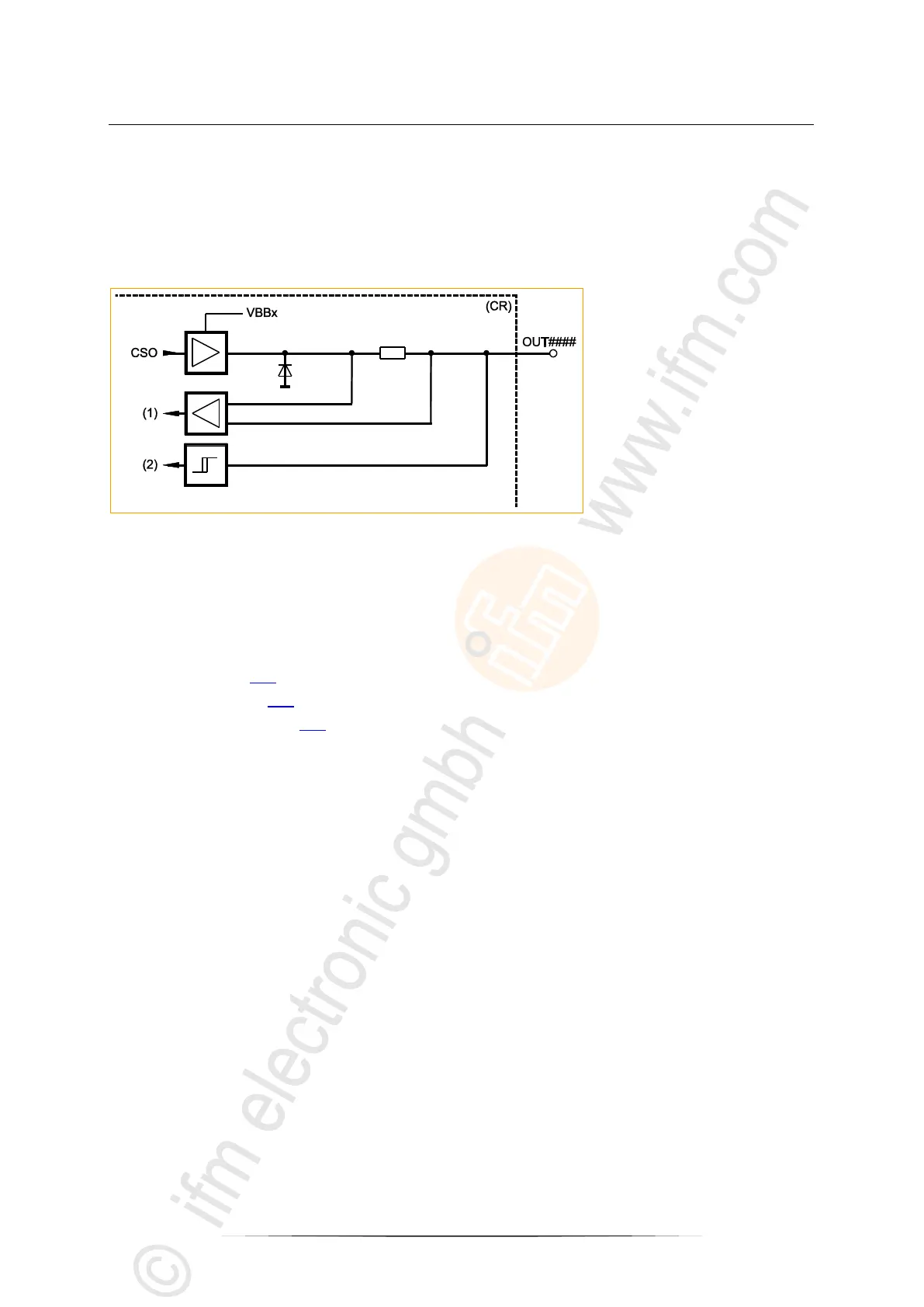
Block diagram
OUT PWM-n-A
OUT#### = connection of PWM output no. ####
(CR) = device
(1) = measured value (analogue)
(2) = measured value (binary)
Configure input → Chapter System configuration
Possible operating modes:
Binary output CSO (B
H
)
analogue output CSO with pulse width modulation (PWM
H
)
analogue output CSO with pulse width modulation, current-controlled (PWM
I
)
Setting and measurement via:
FB Output (→ p. 128)for binary output
FB PWM1000 (→ p. 156) for PWM
FB CurrentControl (→ p. 153) for current control (PWM
I
)


 To Next Page