2
4
5
3
7
8
6
1
2
4
5
6
3
1
7
8
18 19
17
22
4
FLUE INSTALLATION
For the Victrix Pro V2 180 EU model, cascade fume exhaust is not
provided.
4.1 INSTALLATION RECOMMENDATIONS
- the generators must be positioned on the same horizontal line;
- the exhaust manifold must have a minimum inclination of 5%;
- the drain for the condensation water produced by the appliances must ow out
according to the local legislation in force, based on the installed output;
Check and if necessary regulate the heating capacity of each indi-
vidual appliance (see heat output regulations paragraph in the boiler
instructions manual).
Before assembly, check that the seals are positioned correctly (see Fig.
17) and lubricate them with the paste supplied with the kit.
Condensate drain. To drain the condensate produced by the appliance, it is
necessary to connect it by acid condensate-resistant pipes, using the drain trap
(8). e connection must be set up so as to prevent the liquid in it from freezing.
Before appliance start-up, ensure that the condensate can be correctly removed.
Also, comply with national and local regulations on discharging waste waters.
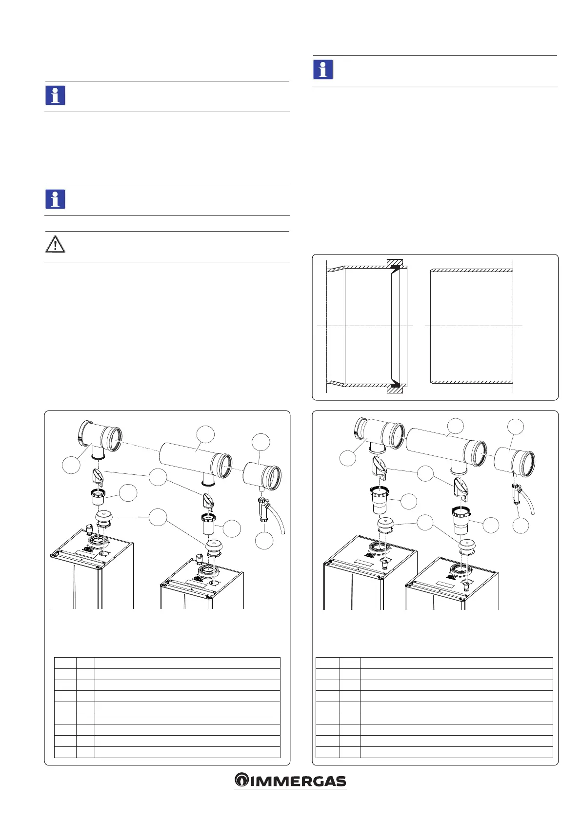
boiler 1 boiler 2 boiler 1 boiler 2
Composition of manifold kit Ø 160 ue exhaust Victrix Pro V2 35-55-
60-68-80 EU
Ref. Qty Description
1 2 Intake stub pipe kit Ø 80
2 1 Vertical stub rst boiler connection Ø 80
3 1 Vertical stub second boiler connection Ø 80
4 2 Clapet valve Ø 80
5 1 Smoke duct closing cap Ø 160
6 1 Second boiler connection manifold Ø 160
7 1 Manifold with condensate drain Ø 160
8 1 Condensate drain trap
e “green series” manifold cannot be installed externally without
suitable protection against UV rays and other eects of the weather.
4.2 FLUE EXHAUST MANIFOLD KIT ASSEMBLY
Replace the intake closing cap on the boiler with the intake stub kit (1).
Insert connections (2) and (3) on the anges of the respective boilers to the end
stop.
Place the clapet valve (4) on the respective connections (2) and (3), taking care
to orientate the clapet valve correctly. (g. 5 and 6).
Connect the rst boiler manifold (5) to the connection (2) and secure them by
the ring nut.
Connect the second boiler manifold (6) to the rst boiler manifold (5) and secure
it to the connection (3) using the ring nut.
Connect the manifold with condensate drain (7) to the manifold (6).
Now connect the condensate drain trap (8) to the manifold (7).
Composition of manifold kit Ø 200 ue exhaust Victrix Pro V2 100-120-
150 EU
Ref. Qty Description
1 2 Intake stub pipe kit Ø 100
2 1 Vertical stub rst boiler connection Ø 110-125
3 1 Vertical stub second boiler connection Ø 110-125
4 2 Clapet valve Ø 125
5 1 Smoke duct closing cap Ø 200
6 1 Second boiler connection manifold Ø 200
7 1 Manifold with condensate drain Ø 200
8 1 Condensate drain trap






 To Next Page