40
H
K
Q
I
I
G
P
J
R
S
T
R
T
S
R
T
S
R
T
S
53
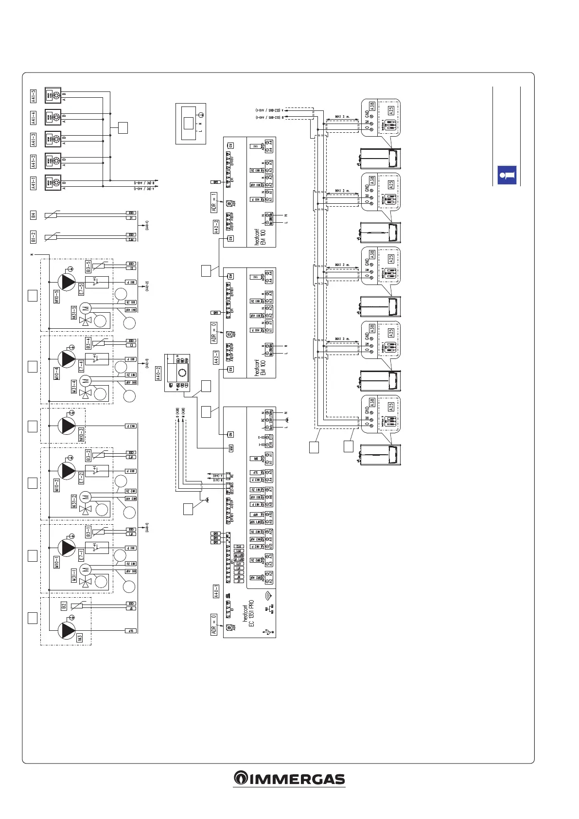
6.4 WIRING DIAGRAM WITH CASCADE REGULATOR AND VPV2 ZONES 3.034119 FIVE HEATING ZONES FOUR MIXED AND ONE
DIRECT WITH DOMESTIC HOT WATER STORAGE TANK
See notes on next
page.
Key:
A25 - CLIP-IN (not standard on
VPV2 devices)
A40-1 - Cascade and zone regu-
lator VPV2 (heatcon! EC
1351 pro)
A40-2 - Cascade and zone regula-
torVPV2 (heatcon! MMI
200)
A41-... - Zone manager VPV2
(heatcon! RC 130)
A38 - Connection card (signals)
A42-1 - Expansion for Victrix Pro
V2 cascade regulator zone
4 (heatcon! EM 100)
A42-2 - Expansion for Victrix Pro
V2 cascade regulator zone
5 (heatcon! EM 100)
B1-2 - System ow side probe
(PTC)
B2 - DHW probe (storage tank
unit) (PTC)
B3-1 - Low temperature ow
probe (Zone 1) (PTC)
B3-2 - Low temperature ow
probe (Zone 2) (PTC)
B3-4 - Low temperature ow
probe (Zone 4) (PTC)
B3-5 - Low temperature ow
probe (Zone 5) (PTC)
B4 - External probe (PTC)
E7-1 - Low temperature safety
thermostat (Zone 1)
E7-2 - Low temperature safety
thermostat (Zone 2)
E7-4 - Low temperature safety
thermostat (Zone 4)
E7-5 - Low temperature safety
thermostat (Zone 5)
M3 - Boiler unit supply pump
(230 Vac)
M10-1 - Central heating circuit
pump zone 1 (230 Vac)
M10-2 - Central heating circuit
pump zone 2 (230 Vac)
M10-3 - Central heating circuit
pump zone 3 (230 Vac)
M10-4 - Central heating circuit
pump zone 4 (230 Vac)
M10-5 - Central heating circuit
pump zone 5 (230 Vac)
M31-1 - Mixing valve zone 1 (230 Vac)
M31-2 - Mixing valve zone 2 (230 Vac)
M31-4 - Mixing valve zone 4 (230 Vac)
M31-5 - Mixing valve zone 5 (230 Vac)
G - e shielding must be connected to earth only
on one side (for example this one)
H - US cable cross-section: 0.5 mm
2
(Maximum
admissible length: 100 m (2 x 100 m))
I - Cable with 4-pole connector (length: 25 cm)
(Supplied with EM 100)
J - BUS cable: J-Y(St)Y 2x2x0.6 (Max. permissi-
ble length: 50 m (2 x 50 m))
K - 230 Vac - 50 Hz power supply
P - Note: in case there are communication problems
between the heatcon! EC and Victrix Pro V2, connect
the GND of all devices to the GND of the EEZ-BUS.
e GND connection must not be carried out via
the braid, but using the other pair of twisted cables
present inside the J-Y (St) Y 2x2x0.6 type cable.
Q - Flat cable (length: 70 cm) (on the MMI 200)
R - Close
S - Open
T - Common
U - Zone 4
V - Zone 5
W - Zone 2
X - Zone 3
Y - Storage tank unit
Z - Zone 1






 To Next Page