37
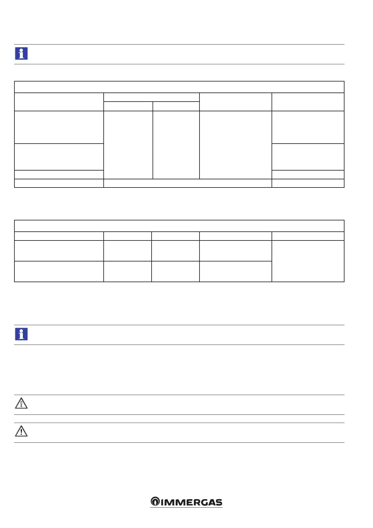
5.10 TABLES AND NOTES COMMON TO SIMPLE CASCADE WIRING DIAGRAMS
e tables and notes in this paragraph apply to the diagrams in Fig. 25-26-27-28-29-30-31-32.
• Type and size of connecting cables
ELECTRICAL CONNECTIONS (SIGNALS)
Components
Cable gauge (mm
2
)
Cable diameter (mm) Maximum length (m)
minimum maximum
• B1-2
• B2
• B3
• S50
• 0-10V
0.5 1.5 5 - 7
25 (2x25)
• B4
• S20-1
• S20-2
• Openerm
50 (2x50)
• External reset 10 (2x10)
• A27 J-Y(ST)Y 2x0,6 50 (2x50)
Note: Screw terminal blocks for electrical connection (loads) accept a maximum cable gauge of 1.5 mm
2
and a minimum of 0.5 mm
2
.
• Maximum loads on relays
MAXIMUM LOADS ON RELAYS OF BOARDS A2 AND A4
Multifunction relay Voltage Current Cosφ Maximum length (m)
K70-A2/K70-A3
K70-A4/K70-A5
K70A1
230 Vac < 0.1 A ≥ 0.6
From factory settings, K70 relays
do not perform any functions.
Insert an optional external relay
to drive each load.
K70-A6/K70-A7
Potential-free
contact
(230 Vac MAX)
< 0.1 A ≥ 0.6
• Notes
- the 'ERROR' signal lamp congured on any relay of the Master appliance is activated in the presence of faults detected along the Cascade;
- the 'Burner on' signal lamp congured on relays K70-A6 and K70-A7 of the Master boiler is activated when one or more burners are lit in the Cascade.
For more details on warning lights, see section 5.4.
Remove X40 bridge in case of connection:
• Cascade and zone regulator
• 0-10V
• BMS
• BUS OT
• Certain types of heating request ("Heating request type" parameter in the "Hydraulic settings" menu)
For low-temperature zones, insert a safety thermostat in series with the relative zone pump.
When conguring the mixing valve, use the relays on the main board (relays K70-A1 to K70-A5)
or on the display board (relays from K70-A6 and K70-A7).
Do not use a relay on the main board and one on the display board.






 To Next Page