13
6
12
12
12
9
10
11
14
15
7
8
1
1
1
22
25
4.5 ASSEMBLY OF ADDITIONAL BOILER MANIFOLD KIT FOR VICTRIX PRO V2 150 EU
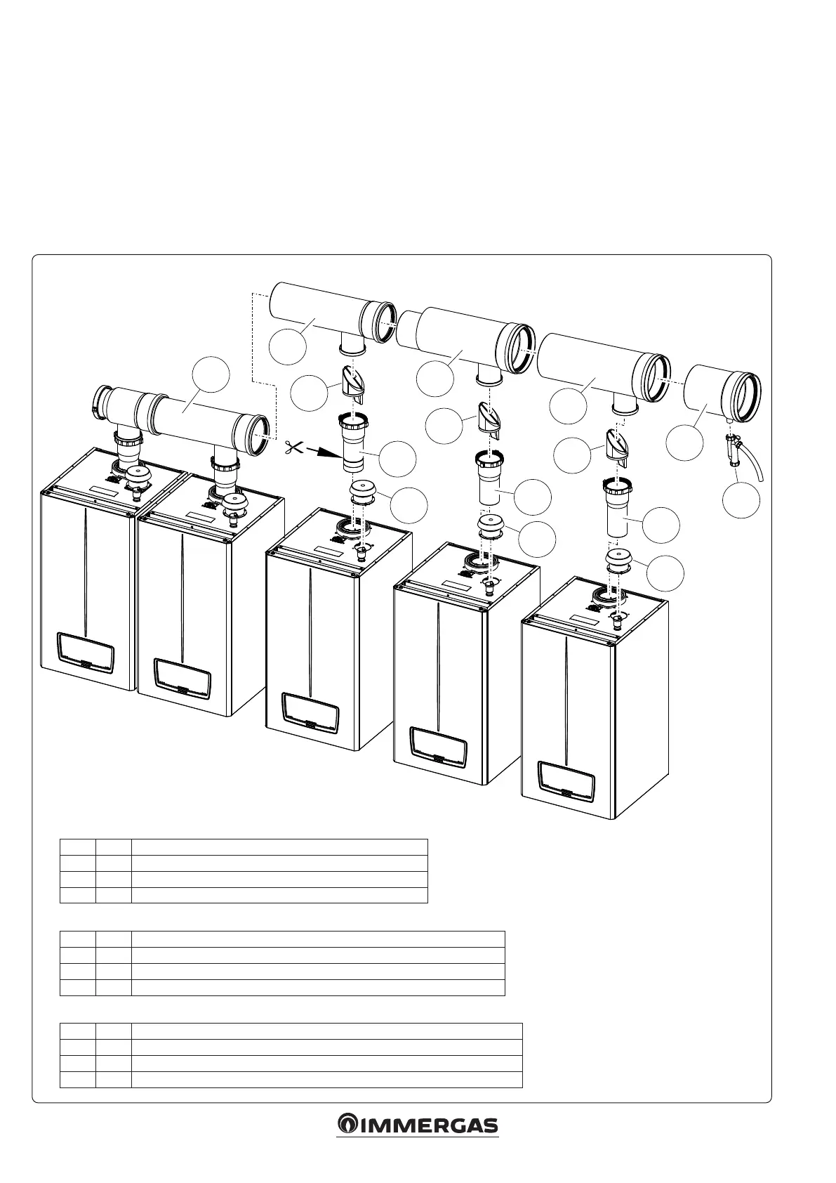
e extension kits make it possible to complete cascade installation, and you must have one for each boiler being connected, according to gure 22 (max of 5 boilers
in cascade).
Replace the intake closing cap on the boiler with the intake stub kit (1).
Cut o the connection (9) as shown in the gure and engage it on the third boiler, bringing it to a stop.
Next, engage the other connections (10) and (11) on the respective boilers to the end stop, taking care to orientate the clapet valve (12) correctly
Connect the additional boiler manifold (13) to the manifold (6) and then to the connection (9); the manifold (14) to the manifold (13) and then to the connection (10),
the manifold (15) to the manifold (14) and then to the connection (11) and tighten the ring nut of each connection.
Connect the manifold with condensate drain (7) to the manifold (15).
Now connect the condensate drain trap (8) to the manifold (7).
Manifold kit composition Ø 200 Victrix Pro V2 150 EU additional boiler
Ref. Qty Description
9 1 Boiler connection DN110-125
12 1 Clapet DN125
13 1 Manifold DN200
Manifold kit composition Ø 250 additional boiler for Victrix Pro V2 150 EU (boiler no. 4)
Ref. Qty Description
10 1 Boiler connection DN110-125 (4th boiler)
12 1 Clapet DN125
14 1 Manifold DN200-250 (4th boiler)
Manifold kit composition Ø 250 additional boiler for Victrix Pro V2 150 EU (boiler no. 5)
Ref. Qty Description
11 1 Boiler connection DN110-125 (5th boiler)
12 1 Clapet DN125
15 1 DN250 manifold (5th boiler)
boiler 1
boiler 2
boiler 3
boiler 4
boiler 5






 To Next Page