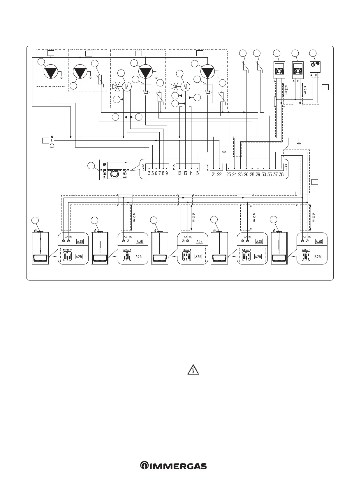
≤ 2 m
≤ 2 m
≤ 2 m
≤ 2 m
≤ 2 m
≤ 2 m
J
J
K
1
2
3
4
5
6
7
8
9
6
10
15
1616
16
1616
18 17
19
17
19
18
38
50
Key:
1 - Central heating circuit pump zone 3 (230 Vac - max 2 A)
2 - Boiler unit supply pump (230 Vac - max 2 A)
3 - Storage tank unit temperature probe (PTC)
4 - Mixing valve zone 1 (230 Vac - max 2 A)
5 - Central heating circuit pump zone 1 (230 Vac - max 2 A)
6 - Safety thermostat mixed zone
7 - Zone 1 temperature probe (PTC)
8 - Mixing valve zone 2 (230 Vac - max 2 A
9 - Central heating circuit pump zone 2 (230 Vac - max 2 A)
10 - Zone 2 temperature probe (PTC)
11 - External probe (PTC)
12 - Common ow temperature probe (PTC)
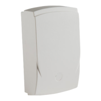
13 - Zone manager
14 - Modulating room thermostat
15 - Cascade and zone regulator
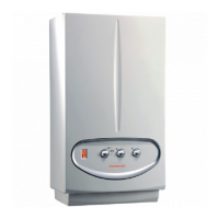
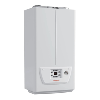
16 - Generator
17 - Close
18 - Open
19 - Common
A25 - CLIP-IN (optional)
A38 - Connection card (signals)
X - Zone 3
Y - Storage tank unit
Z - Zone 1
W - Zone 2
J - BUS cable: J-Y(St)Y 2x2x0.6 (Max. permissible length 50 m)
K - 230 Vac - 50 Hz power supply
Notes:
Remove jumper X40
e parameter 'Heating request type' must be set as 'Room thermostat setpoint'
(default value).
Probe cable gauge: 0.5 mm
2
Maximum permitted length: 100 m
e external probe can be connected to the lower-address appliance as an
alternative to connection to the Cascade and Zone Regulator (order the Immergas
code for the appropriate external probe).
e Cascade and Zone Regulator can deliver a maximum total load
of 6 A.
For this reason, insert an external relay (optional) in series with the
loads .
6.2 WIRING DIAGRAM WITH OLD CASCADE REGULATOR 3.015244 THREE HEATING ZONES TWO MIXED AND ONE DIRECT WITH
DOMESTIC HOT WATER STORAGE TANK






 To Next Page