24
36
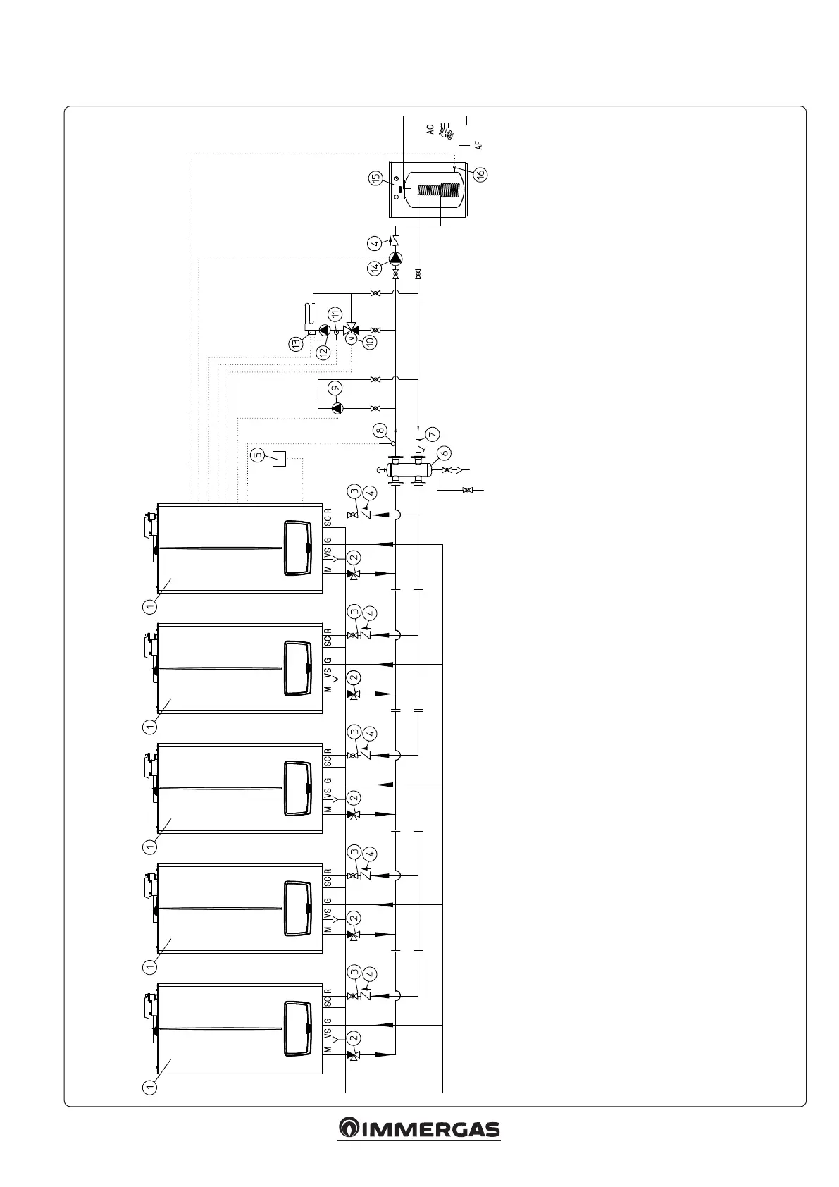
5.9 INSTALLATION DIAGRAM VICTRIX PRO V2 IN SIMPLE CASCADE ONE DIRECT CENTRAL HEATING ZONE AND ONE MIXED HEATING
ZONE WITH DOMESTIC HOT WATER BOILER
Key:
1 - Generator
2 - ree-way draining valve
3 - System interception cock
4 - Non return valve
5 - External probe
6 - Manifold/mixer
7 - Slurry collection system lter
8 - Common ow probe
9 - Direct circuit pump
10 - Mixing valve
11 - Pressure gauge
12 - Manual reset minimum pressure switch
13 - Safety thermostat
14 - Storage tank unit feeding pump
15 - External storage tank unit
16 - Storage tank unit temperature probe







 To Next Page