1
2
3
4
5
32
45
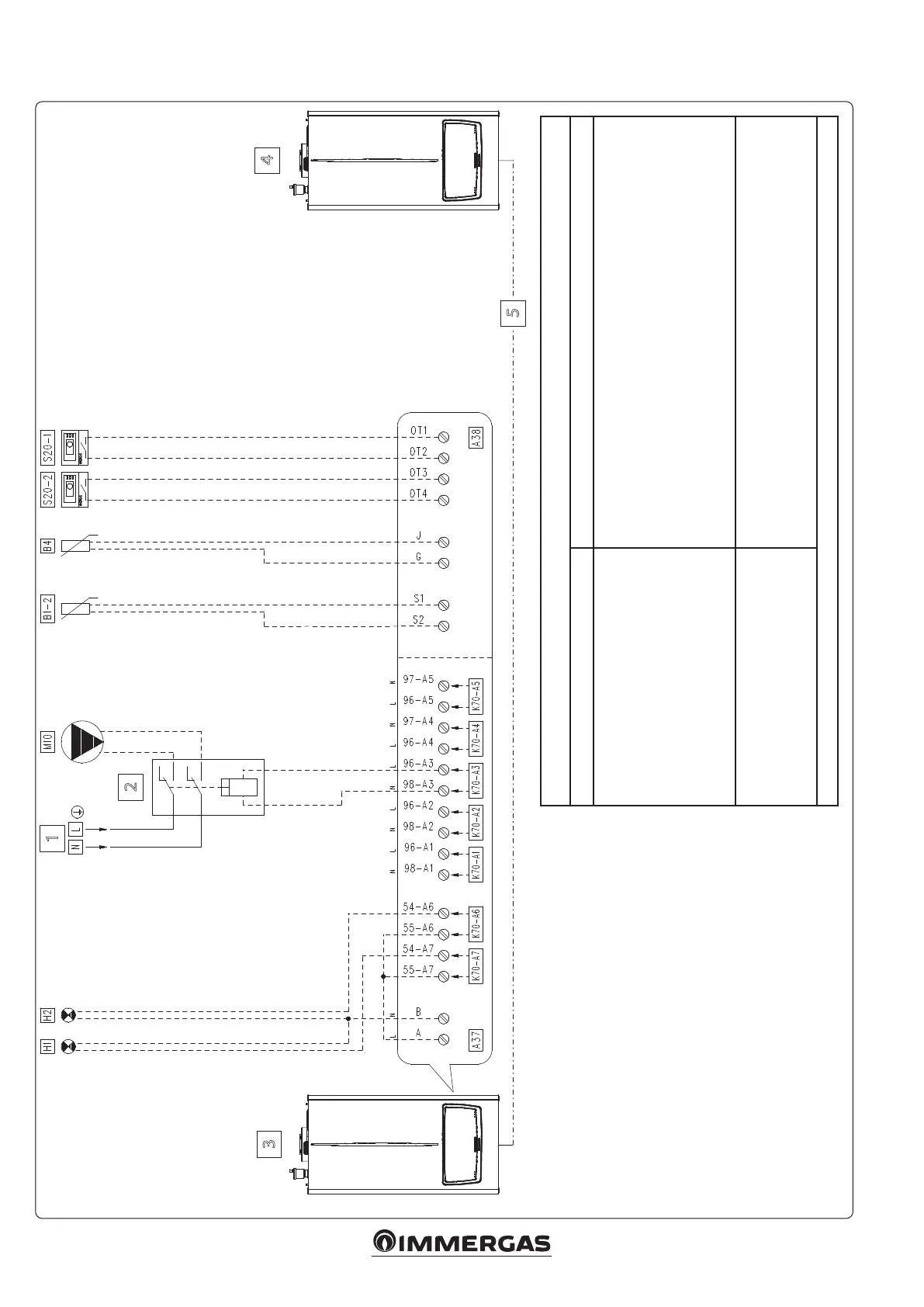
5.18 WIRING DIAGRAM TWO HYDRAULIC ZONES WITH SYSTEM HEATING PUMP
Key:
A37 - Connection sheet (loads)
A38 - Connection card (signals)
B1-2 - System ow probe (NTC) (optional)
B4 - External probe (NTC) (optional)
H1 - “ERROR" warning light (230 Vac) (optional)
H2 - “Burner on” indicator light (230 Vac) (optional)
M10 - Zone circulator (optional)
S20-1 - Zone 1 room thermostat (optional)
S20-2 - Zone 2 room thermostat (optional)
1 - 230 Vac - 50 Hz
2 - External relay (optional) - Coil 230 Vac Max. 0.1 A
3 - Master appliance
4 - Slave appliance (last boiler)
5 - Simple cascade appliance communication BUS
(make connections as per specic diagram)
“HYDRAULIC SETTINGS” PARAMETER CONFIGURATION TABLE ('TECHNICIAN' MENU)
Parameter/menu name Setting
“Relay settings” submenu:
- K70-A1
- K70-A2
- K70-A3
- K70-A4
- K70-A5
- K70-A6
- K70-A7
System pump conguration
- Relay not used
- Relay not used
- System pump
- Relay not used
- Relay not used
- Burner on
- Error
- Zone 1 + Zone 2
- System sensor
- Type of heating request
- DHW request type
- Parallel mode
- C.H. mode
- Outdoor temperature curve and room thermostat
- ermostat (In this case, the diagram does not provide for DHW, but default setting
it as a thermostat avoids error 33)
- Disabled
Note: the system pump is driven by both room thermostats.
Openerm:
• If an Openerm thermostat is used, set the parameter
'Heating request type' as 'Room thermostat setpoint';
• Make sure that the Openerm thermostat is compatible
with the appliance.
Notes:
See further tables and notes pertaining to this scheme in
section 5.10, "Tables and notes common to simple cascade
wiring diagrams".
 Loading...


