2
3
3
4
5
6
≤ 2 m
≤ 2 m
33
46
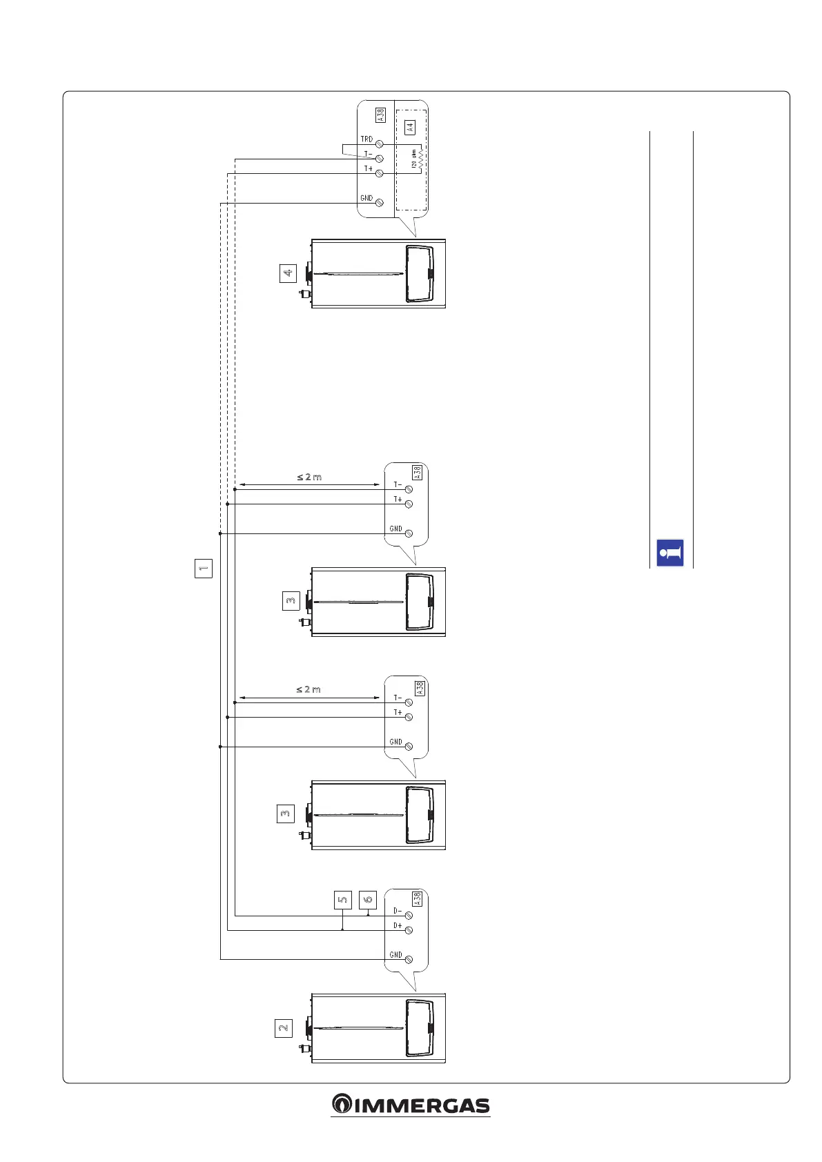
Key:
1 - Cable type: 2 x twisted pair (20 / 22 AWG)*
2 - Master appliance
3 - Slave appliance
4 - Slave appliance (last appliance)
5 - Data +
6 - Date -
*Note: in one pair connect the 'DATA +' and 'DATA -' signals, in the other pair connect the 'GND'
5.19 SIMPLE CASCADE BUS CONNECTION WIRING DIAGRAM
e communication BUS between the devices of the simple cascade is via Modbus protocol (RS485).
e Modbus parameters, which can be congured via “MENU”, have no eect on the simple cascade
but serve for the BMS.
e link between the “TRD” and “T-” terminals is the responsibility of the installer (the
120 ohm resistance is already present on the “Display board”).






 To Next Page