VS GM R RM GVS
4
8
10
6
2
5
7
11
3
AC
AF
SCSC
12
1
SC RM GVSVS GM RSCSC RM GVS
10
9
14
5
1
1 1 1
12 12 12
12
13
10
9
14
10
9
14
10
9
14
10
9
14
23
35
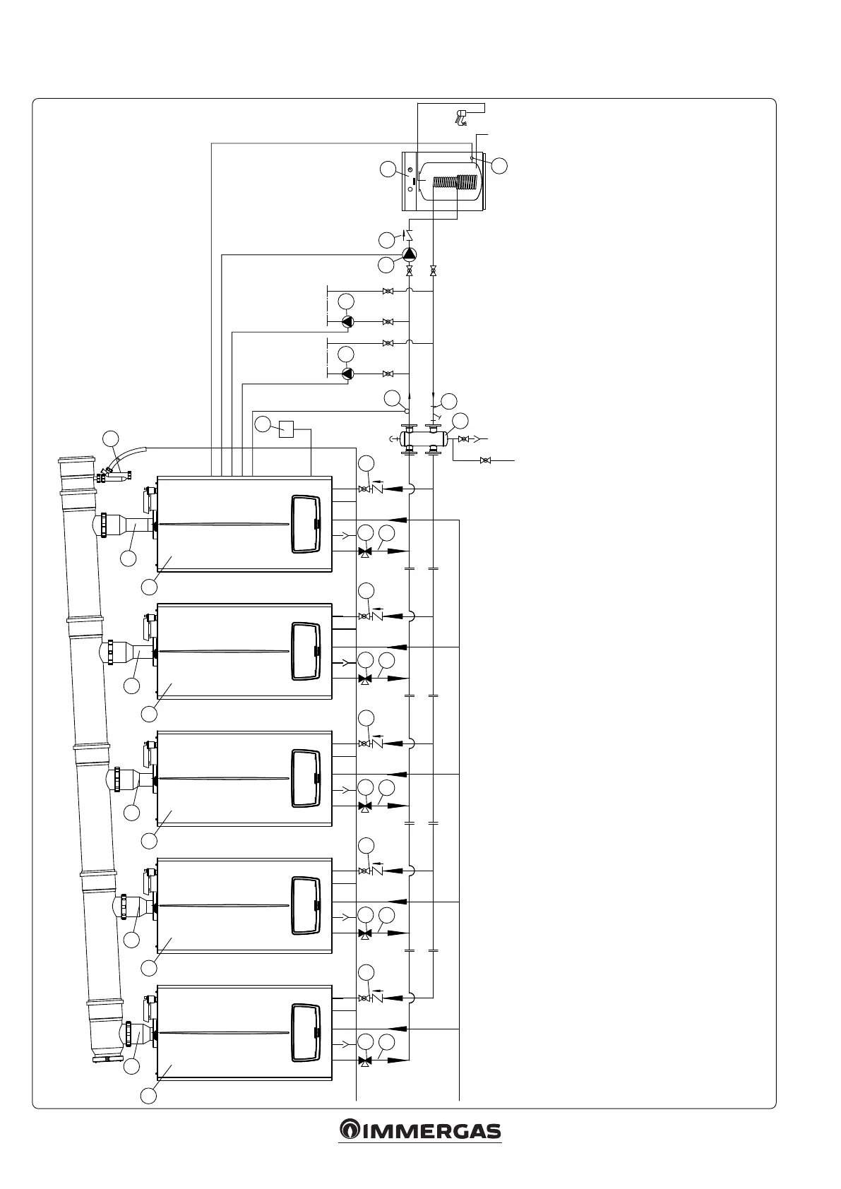
Key:
1 - Generator
2 - External probe
3 - Common ow probe
4 - Storage tank unit temperature probe
5 - Direct circuit pump
6 - Storage tank unit feeding pump
7 - Manifold/mixer
8 - External storage tank unit
9 - ree-way draining valve
10 - Non return valve
11 - Slurry collection system lter
12 - Flue circuit ue adjusting appliance
13 - Stub pipe drain trap
14 - System interception cock
5.8 INSTALLATION DIAGRAM VICTRIX PRO V2 IN SIMPLE CASCADE TWO DIRECT HEATING ZONES WITH DHW TANK
 Loading...


