≤ 2 m
1
5
6
2
3
4
34
47
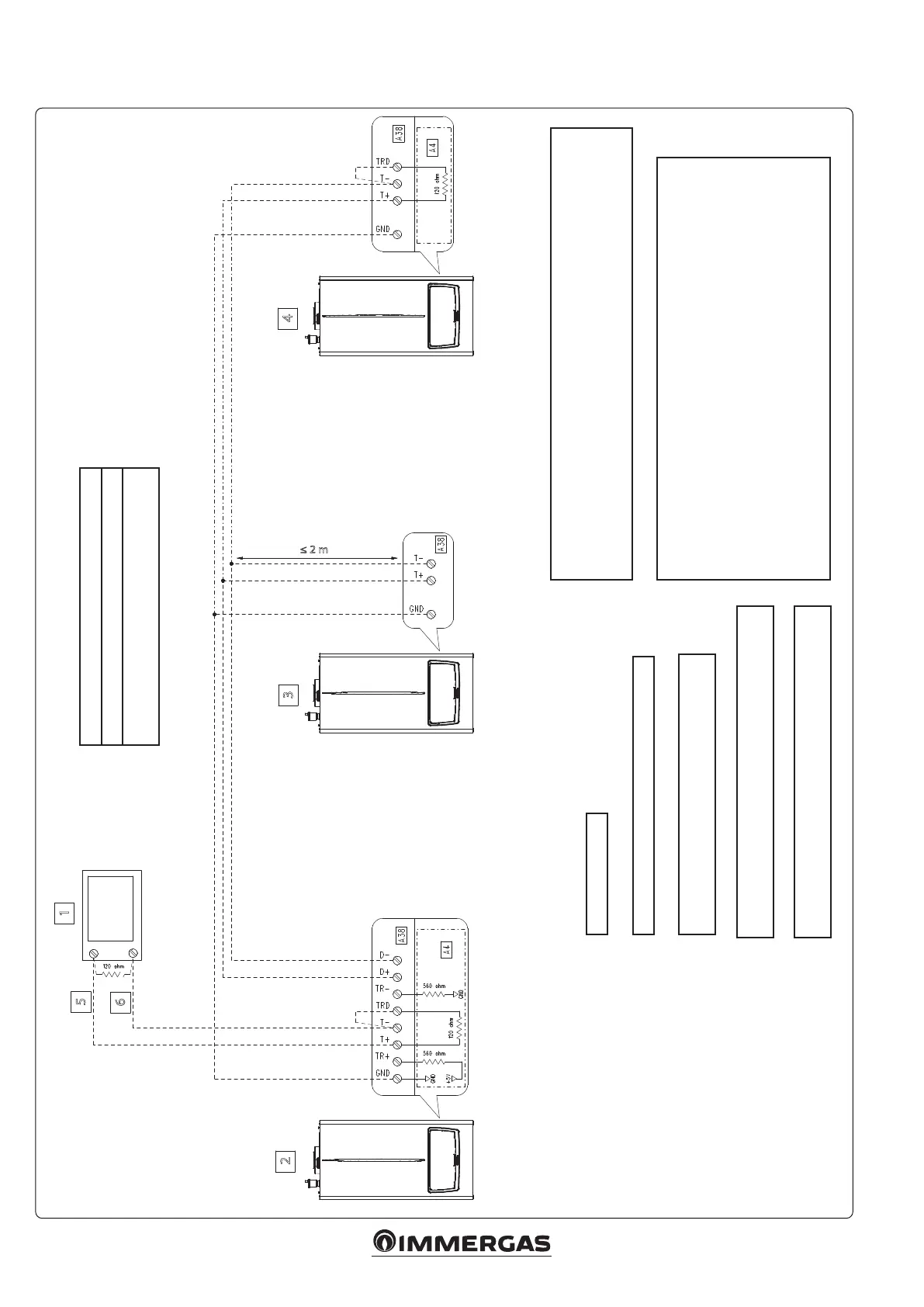
Key:
A4 - Display board
A38 - Connection card (signals)
1 - BMS (Modbus master)
2 - Master generator
3 - Slave generator
4 - Slave generator (last appliance)
5 - Data +
6 - Date -
SIMPLE CASCADE
Cable type: 2 x double braided (20 / 22 AWG)
Note: in one pair connect the 'DATA +' and 'DATA -'
signals, in the other pair connect the 'GND'
Cable type (BMS): twisted pair (20 / 22 AWG)
BUS: Modbus parameters can be found in the 'TECHNICIAN/
SYSTEM SETTINGS/Modbus parameters' MENU
The parameter 'Heating request type' must be set as 'Room
thermostat setpoint' (default value)
Modbus parameters have no eect on the
Simple cascade
Remove jumper X40
It is possible to connect the following sensors to the Master appliance and read them via BUS:
- System ow probe (B1-2)
- External probe (B4)
- DHW probe (B2)
- DHW ermostat/Contact (S50)
5.20 WIRING DIAGRAM CONNECTION TO BMS SIMPLE CASCADE
BMS: on one side of the bus, there must be a pull up resistance and a pull down resistani-
ce.
e diagram assumes that the two pull up and pull down resistances are already present
in the external device (box 1 in the gure 34); if these resistances are not present on the
external device, it is necessary to make the link between the TR+ terminals with T+ and
TR- with T-, so as to use the pull up and pull down resistances already present on the
display board (A4).
e termination resistance (120 ohm) is required on both sides of the BUS; to achieve
this, the installer must t the 120 ohm resistance (not supplied) on the external device
(box 1 in g. 34) and then make the link between the TRD and T- terminals, so as to use
the resistance already present on the display board (A4).






 To Next Page