)C°(snoitacificepSlamrehT384MI
noitacificepS
egnaR
erutarepmeTtneibmA °05+ot°0
erutarepmeTegarotS
°521+ot°04-
erutarepmeTetalPmumixaM °07+
Table 2.2: IM483 Thermal Specications
NOTE! Additional cooling may be required to limit the plate
temperature to 70°C! An optional heat sink and thermal pad is
available, see Appendix C: Cooling Solutions for details.
P i n A s s i g n m e n t a n d D e s c r i p t i o n
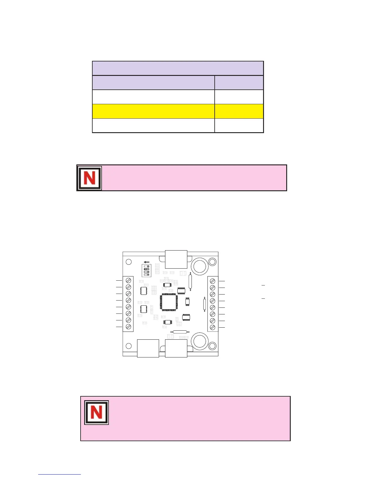
Figure 2.2: IM483 Pin Conguration
NOTE! This pin conguration diagram and table represent
the pinout of any 8 position connector used for P1. If you
purchased the IM483-34P1 option (34 Position Header) the
pin conguration diagram and table is located in Appendix A:
Standard Connection Options.
MSEL0
MSEL1
MSEL2
MSEL3
ON
SW1
P1 P2
N/C - P1:1
Step Clock - P1:2
Direction - P1:3
Opto Supply - P1:4
Enable - P1:5
Reset - P1:6
Fault Output - P1:7
On-Full-Step Output - P1:8
P2:8 - Motor Ø A
P2:7 - Motor
Ø
P2:6 - Motor Ø
B
P2:5 - Motor Ø
P2:4 - +V (+12 to +48 VDC)
P2:3 - Ground
P2:2 - Current Adjust
P2:1 - Current Reduction Adjust
A
B