71IM483 Operating Instructions Revision R032306
B B - 3 4 - 4 P B r e a k o u t B o a r d
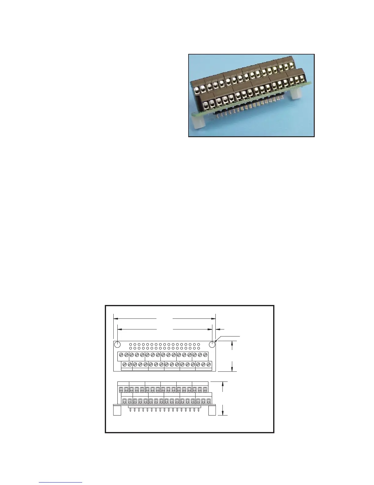
The BB-34-4P breakout board
is designed to provide a screw
terminal interface for the IM483-
34P1, IM483I, IM483IE and
IM804/805-34P1 microstepping
driver.
This interface is easily inserted
into the P1 pin receptacle.
M e c h a n i c a l
S p e c i f i c a t i o n s a n d
W i r i n g R e c o m m e n d a t i o n s
IMS recommends that the following wiring practices be used to interface to
the IM483-34P1 using the BB-34-4P:
n Wire Size: 16 - 22 AWG
n Strip Length: 0.200” (5mm)
n Screw Torque: 3.0 lb-in (0.33 N-m)
Mechanical specications are illustrated in Figure D.4.
I n s t a l l a t i o n
To install the BB-34-4P rst remove the 34 pin header from the receptacle by
gently rocking it back and forth and lifting the pin header straight upwards.
Do not remove at a side-to-side angle.
Insert the breakout board into the P1 pin receptacle as shown in Figure
D.6. Mount to drive and heat sink plate using the recommended mounting
hardware.