41IM483 Operating Instructions Revision R032306
I n t e r f a c i n g a n d U s i n g t h e I s o l a t e d L o g i c
I n p u t s
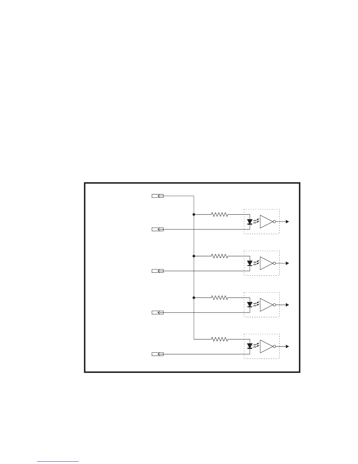
The IM483 has 4 optically isolated logic inputs which are located on
connector P1. These inputs are isolated to minimize or eliminate electri-
cal noise coupled onto the drive control signals. Each input is internally
pulled-up to the level of the optocoupler supply and may be connected
to sinking outputs on a controller such as the IMS LYNX or a PLC. These
inputs are:
1] Step Clock (P1:2)
2] Direction (P1:3)
3] Enable (P1:5)
4] Reset (P1:6)
Of these inputs only step clock and direction are required to operate the
IM483.
The schematic shown in Figure 7.5 illustrates the inputs.