EasyManua.ls Logo

IMS IM483 - Figure 7.9 LYNX Interface

IMS IM483
83 pages
Print Icon
To Next Page IconTo Next Page
To Previous Page IconTo Previous Page
Loading...
46 IM483 Operating Instructions Revision R032306
47IM483 Operating Instructions Revision R032306
I M 4 8 3 I n t e r f a c e d t o a n I M S LY N X
The LYNX Controller is a powerful, machine control solution which can
be used to meet the system design needs of a wide range of applications.
It has the capability of controlling up to three axes sequentially when
used with the optional high speed differential I/O module. For more
information on the LYNX, brows
e the IMS web site at www.imshome.com.
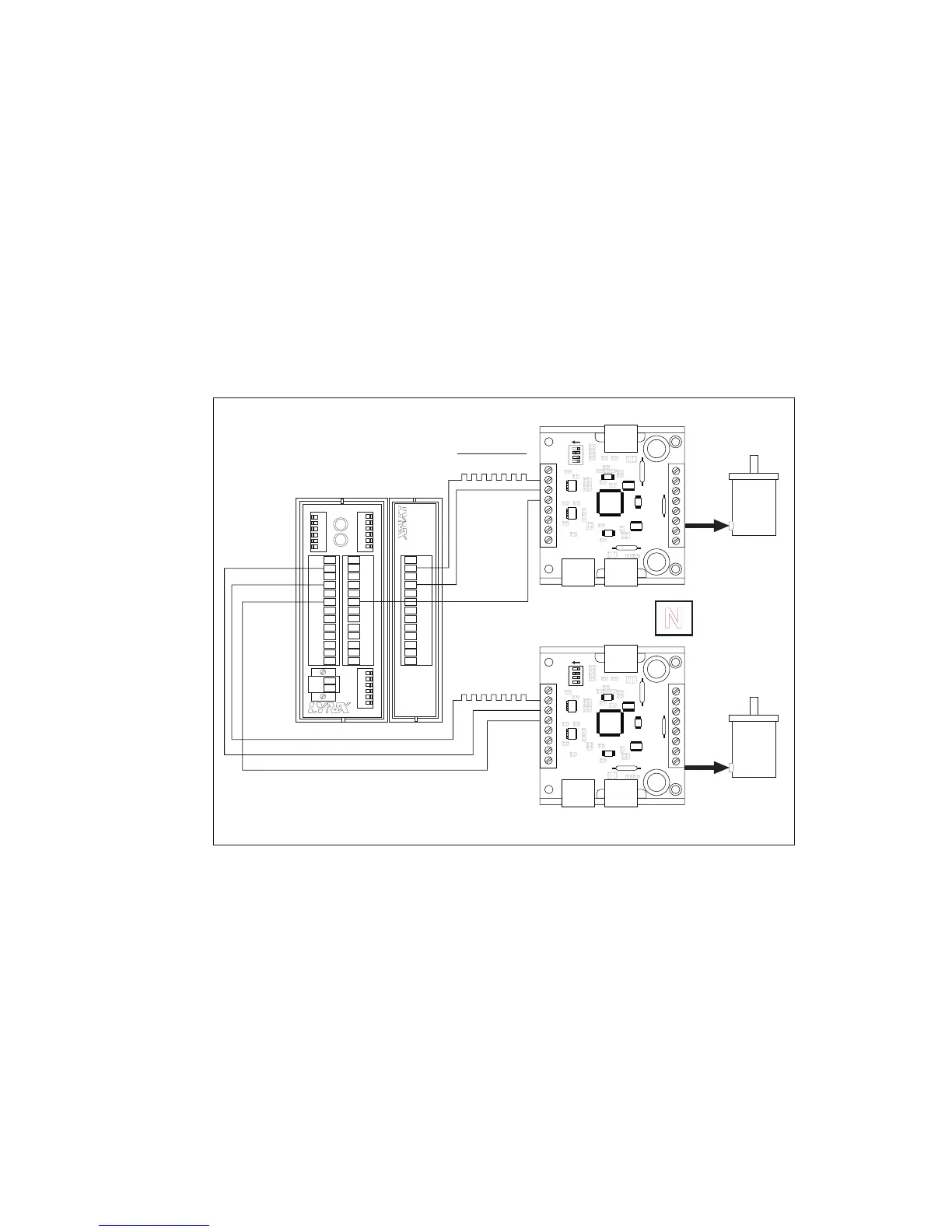
Figure 7.9 shows a LYNX Control Module and Differential I/O Module
providing step clock, direction and optocoupler supply voltage to two
IM483 drivers. The LYNX isolated I/O may also be used to control the
enable and reset inputs, the MSEL inputs (IM483-34P1) and receive feed-
back from the fault and fullstep outputs.
IM483 Driver #1
IM483 Driver #2
+5VDC Opto Supply
+5VDC
Opto Supply
Step Clock Input
Direction Input
SCLK+
DIR+
+5VDC
OUTPUT
DIR+
DIR-
SCK-
SCK+
GND
+5V
RX-
RX+
TX-
TX+
CGND
RX
TX
22
21
23
24
25
26
31
32
33
34
35
36
IG
INTELLIGENT MOTION SYSTEMS, INC.
FAULT
POWER
1
2
3
4
5
6
1 2 3 4 5 6
1 2 3 4 5 6
22
21
23
24
25
26
31
32
33
34
35
36
GND
V+
A1
A0
A2
PT
HI
UG
TM
Differential/O
MODULE
TM
13+
13-
14-
14+
15-
15+
16-
16+
17-
17+
18-
18+
GD
Stepping
Motor #2
N
Power Connections
Not Shown For
Simplification
MSEL0
MSEL1
MSEL2
MSEL3
ON
SW1
P1 P2
MSEL0
MSEL1
MSEL2
MSEL3
ON
SW1
P1 P2
Stepping
Motor #1
HSI/O Drive #2
13+ Step Clock
14+ Direction
Figure 7.9: LYNX Interface

Table of Contents

Other manuals for IMS IM483

Related product manuals