47IM483 Operating Instructions Revision R032306
C o n n e c t i n g a n d U s i n g t h e F a u l t O u t p u t
The IM483 has an open collector fault output located on P1:7. This
output is non-isolated and has the ability of sustaining maximum driver
voltage. It can sink a maximum of 25mA, which is sufcient to drive an
LED or a small relay.
This output is active when in a LOW state. The following conditions will
cause this output to become active:
1] Phase-to-phase short circuit.
2] Phase-to-ground short circuit.
3] Phase over-current condition.
When the fault output becomes active, it disables the driver outputs and
latches in this condition. It can only be cleared by toggling the reset input
LOW, or by powering OFF then powering ON the drive.
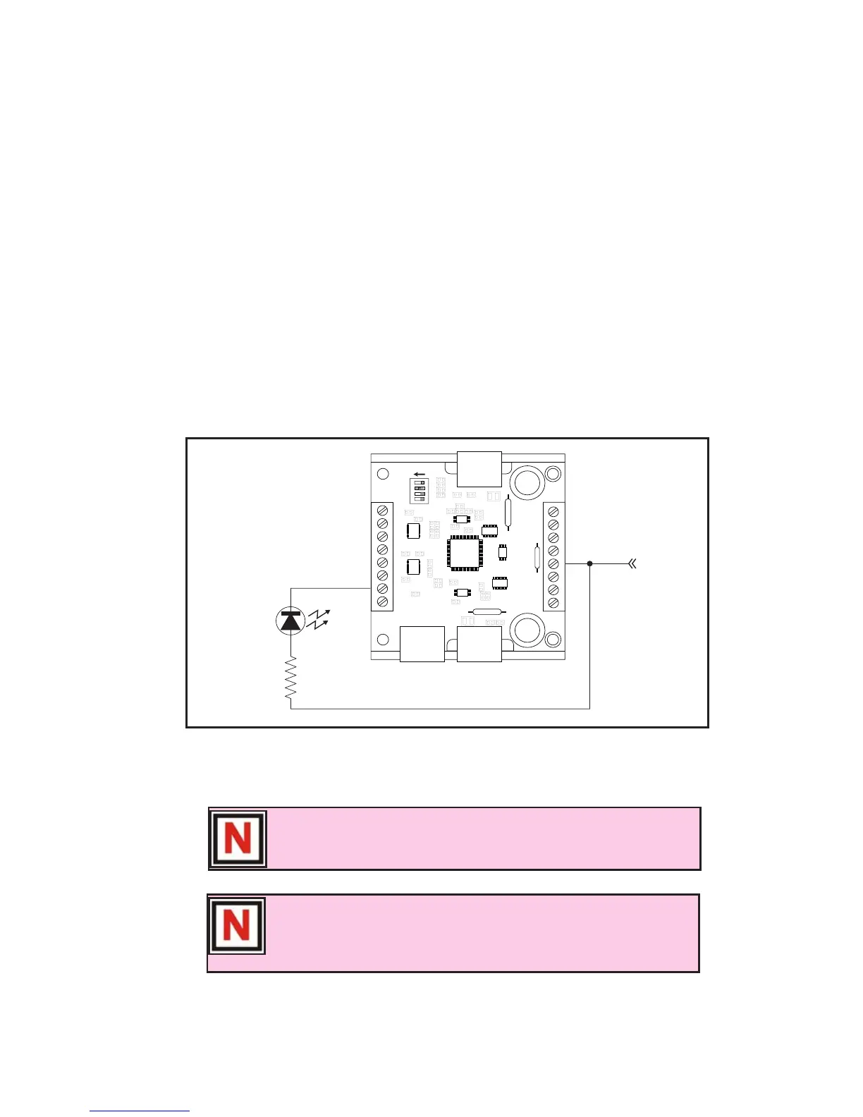
Figure 7:10 illustrates the fault output connected to an LED.
Figure 7.10: The Fault Output Connected to an LED
NOTE! Once the fault output is active, it can only be cleared by
toggling the reset input LOW, or by powering off the driver.
NOTE! The IM483 driver outputs will disable in the event of
an over-temperature condition, however, in this case the fault
output WILL NOT latch. The driver will begin operating again
when the temperature drops below the shut-off threshold.