EasyManua.ls Logo

IMS IM483 - Im483-34 P1-8 P2; Figure A.8 IM483-34 P1-8 P2 - Connector P1; Figure A.9 IM483-34 P1-8 P2 - Connector P2

IMS IM483
83 pages
Print Icon
To Next Page IconTo Next Page
To Previous Page IconTo Previous Page
Loading...
62 IM483 Operating Instructions Revision R032306
63IM483 Operating Instructions Revision R032306
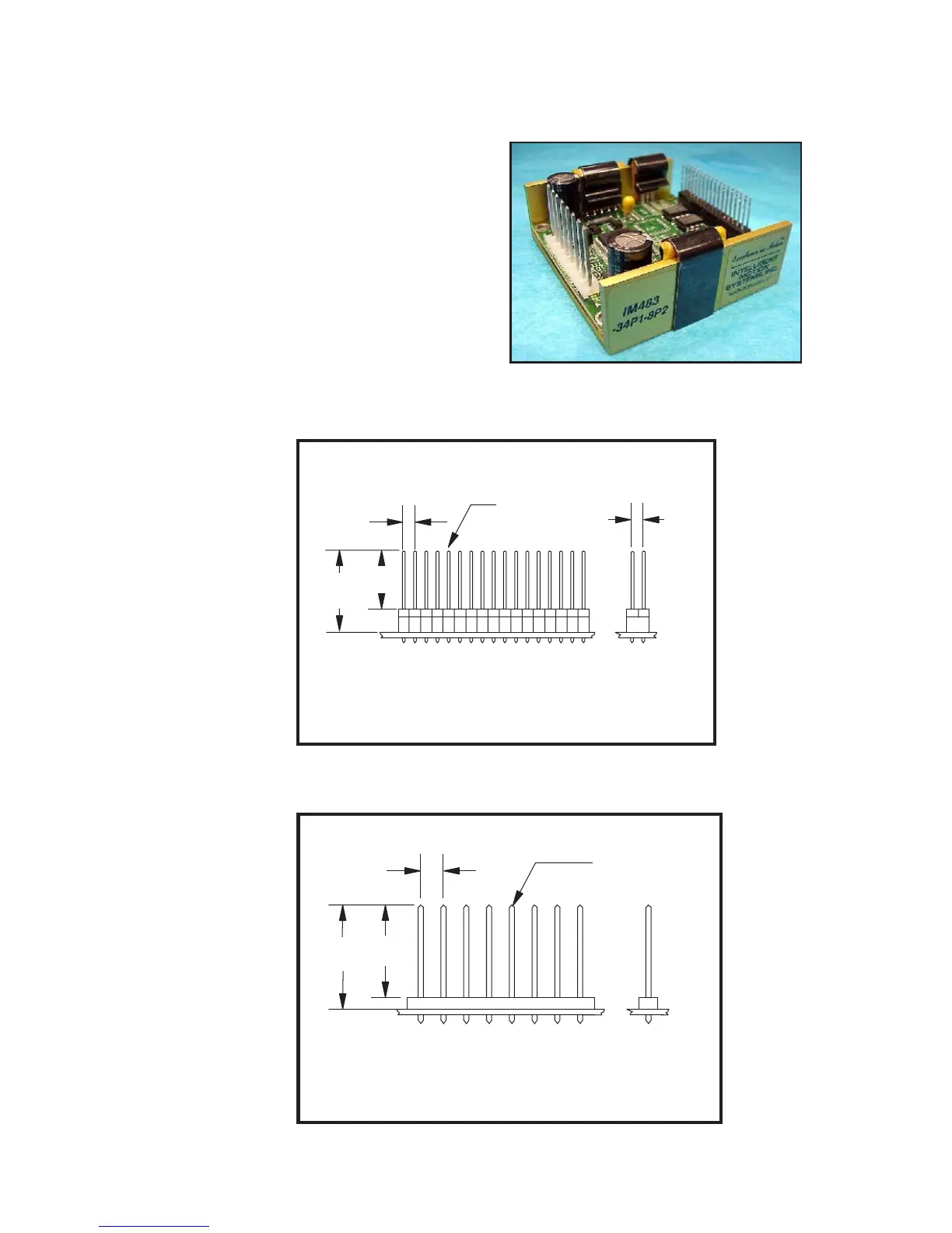
I M 4 8 3 - 3 4 P 1 - 8 P 2
This option combines the features and potential uses of the IM483-34P1
and the IM483-8P2. The connec-
tor pins used for connector P2
are identical to those used on the
IM483-8P2. The difference between
the P1 connector on this model
and the standard IM483-34P1 is in
the pin height of the pin header
shipped with the drive. There is no
difference in the receptacle used.
This option may be solder-mount-
ed or the pins may be wire-
wrapped for interfacing.
0.811
(20.62)
0.914
(23.16)
0.200
(5.08)
8X 0.045 (1.14)
Sq. Post
Ti
n Plated Bronze
Applicable Products:
IM483-8P2
IM483-34P1-8P2
8 Pin Connector Pins - P2
0.520
(13.21)
0.800
(20.32)
0.100
(2.54)
0.100
(2.54)
8X 0.025 (0.64)
Sq. Post
Ti
n Plated Bronze
Applicable Products:
IM483-34P1-8P2
34 Pin Connector Pins - P1
Figure A.8: IM483-34P1-8P2 - Connector P1
Figure A9: IM483-34P1-8P2 - Connector P2

Table of Contents

Other manuals for IMS IM483

Related product manuals