55IM483 Operating Instructions Revision R032306
I M 4 8 3 - 3 4 P 1
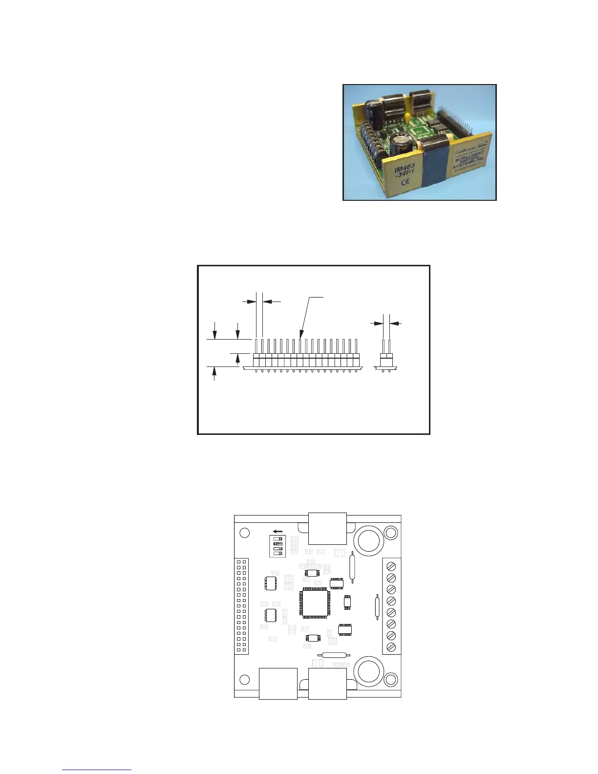
The IM483-34P1 connector congu-
ration replaces the 8 position screw
terminal at connector location P1 with
a 34 pin header. Connector P2 is still an
8 position screw terminal.
There are 2 key features that are added
with this connector option:
1] Microstep resolution
select inputs (MSEL)
on P1 allow for remote
control of the output
resolution.
2] Step/Direction outputs follow the step/direction inputs, allow-
ing for multiple drives to be cascaded.
Figure A.2: IM483-34P1Connector P1Pin Locations
P i n C o n f i g u r a t i o n / D e s c r i p t i o n
Figure A.2 and Table A.1 show the pin location and description of the 34 pin