72 IM483 Operating Instructions Revision R032306
73IM483 Operating Instructions Revision R032306
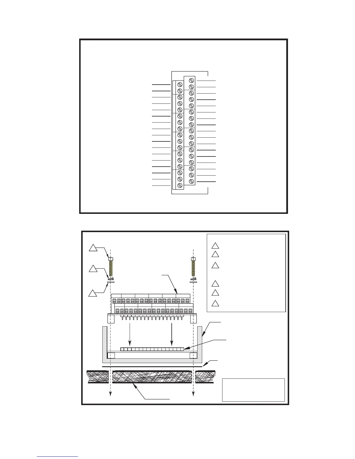
IM483-34P1 CONNECTIONS
See Operating Instructions for Pin Description & Electrical Specifications
1
18
17
34
Pin 1: N/C
Pin 2: N/C
Pin 3: MSEL 3
Pin 4: Step Clock Input
Pin 5: N/C
Pin 6: Direction Inpu
t
Pin 8: Opto Supply
Pin 10: Enable Input
Pin 12: Reset Inpu
t
Pin 14: Fault Output
Pin 16: On-Full-Step Output
Pin 7: N/C
Pin 9: N/C
Pin 11: N/
C
Pin 13: N/C
Pin 15: N/
C
Pin 17: N/C
N/C:
Pin 18
N/C:
Pin 19
N/C: Pin 20
Step Clock Output: Pin 21
Direction Output:
Pin 22
MSEL
0: Pin 23
MSEL
1: Pin 25
Ground: Pin 27
N/C:
Pin 29
N/C:
Pin 31
N/C:
Pin 33
MSEL
2: Pin 24
On-Full-Step Output: Pin 26
N/C:
Pin 28
N/C: Pin 30
N/C: Pin 32
N/C:
Pin 34
N/C = No Connection
Heat Sink Plate
Driver
BB-34-4P
Thermal Pad
IMS TN-48
or Equivalent
Mounting Screw Torque:
5.0
to 7.0 lb-in
(0.60
to 0.80 N-m)
Connector P1
A
B
C
Mounting Hardware - U.S.
#6 Stainless Machine Screw
#6
Split Lock Washer
(.04 TH, .24
OD)
#6 Flat Washer, Stainless
(.04 TH, .24 OD)
A
B
C
Mounting Hardware - Metric
#M3 Stainless Machine Screw
#M3
Split Lock Washer
(.08 TH, 6.20
OD)
#M3 Flat Washer, Stainless
(.05 TH, 6.20 OD)
A
B
C
Figure D.5: BB-34-4P Pin Locations
Figure D.6: BB-34-4P Mounting Diagram