I n t e r f a c e M e t h o d s
The isolated logic inputs may be interfaced to the user’s control system
in a variety of ways. In all cases the inputs are normally in a logic HIGH
state when left oating. For purposes of this manual we will show three
interface methods:
1] Switch Interface.
2] Open Collector Interface.
3] TTL Interface.
We will also show IM483 inputs connected to the IMS LYNX modular mo-
tion controller, which is a powerful machine control soulution.
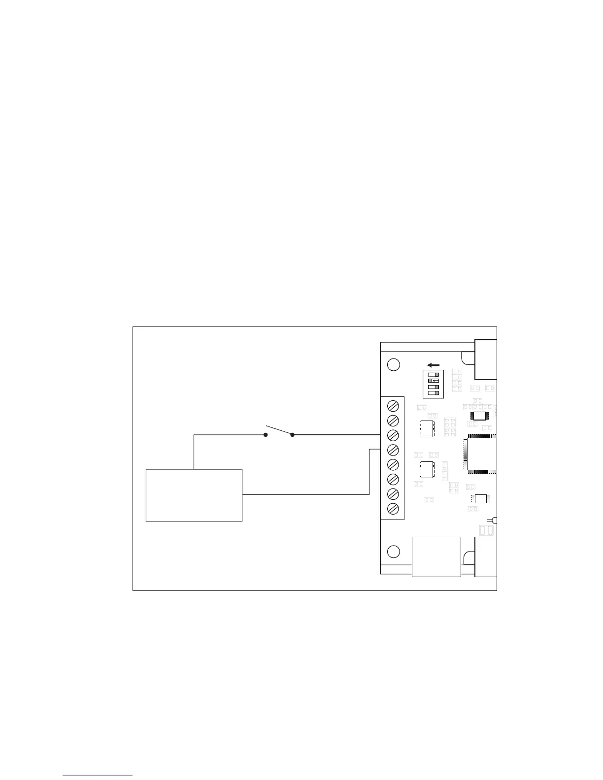
S w i t c h I n t e r f a c e
A switch connected between the input and the opto supply ground will
sink the input. If this method is used a SPST (Single-Pole, Single-Throw)
switch works well for enable and direction. A normally-open momentary
switch works well for reset. Figure 7.6 illustrates a SPST switch connected
to the direction input.