EasyManua.ls Logo

IMS IM483 - Figure 7.7 Open Collector Interface; Figure 7.8 TTL Interface

IMS IM483
83 pages
Print Icon
To Next Page IconTo Next Page
To Previous Page IconTo Previous Page
Loading...
44 IM483 Operating Instructions Revision R032306
45IM483 Operating Instructions Revision R032306
MSEL0
MSEL1
MSEL2
MSEL3
ON
SW1
P1
+VDC
CONTROLLER
OUTPUT
R
W 1
%
LIMIT
+VDC
5
10
12
15
24
-----
681
1000
1300
2670
R
LIMIT
Opto Supply P1:4
Reset P1:6
Low Pulse
Will Reset
Driver
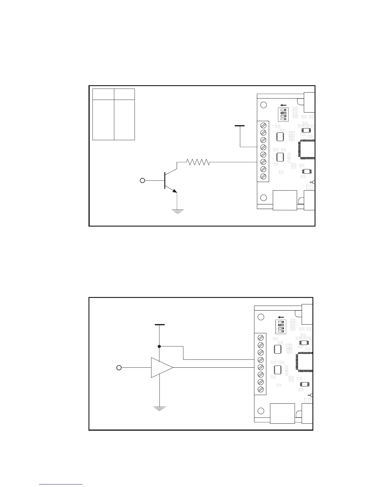
O p e n C o l l e c t o r I n t e r f a c e
Figure 7.7 shows an open collector interface connected to the reset input.
This interface method may be used with any of the logic inputs. Remem-
ber that a current limiting resistor is required if an opto supply voltage
greater than +5 VDC is used.
Figure 7.7: Open Collector Interface
T T L I n t e r f a c e
Figure 7.8 shows a TTL device connected to the enable input. This inter-
face method may be used with any of the logic inputs.
Figure 7.8: TTL Interface
MSEL0
MSEL1
MSEL2
MSEL3
ON
SW1
P1
+5 VDC
CONTROLLER
OUTPUT
Opto Supply P1:4
Enable P1:5

Table of Contents

Other manuals for IMS IM483

Related product manuals