D u a l P W M C i r c u i t
The IM2000 contains a unique dual PWM circuit that efciently and accu-
rately regulates the current in the windings of a two phase stepping motor.
The internal PWM accomplishes this by using an alternating recirculating/
non-recirculating mode to control the current.
R e c i r c u l a t i n g
In a recirculating PWM, the current in the windings is contained within
the output bridge while the PWM is in its OFF state. (After the set current
is reached.) This method of controlling the current is efcient when us-
ing low inductance motors,
but lacks response because
of its inability to remove
current from the windings
on the downward cycle of
the sine/cosine wave (See
Figure 4.1).
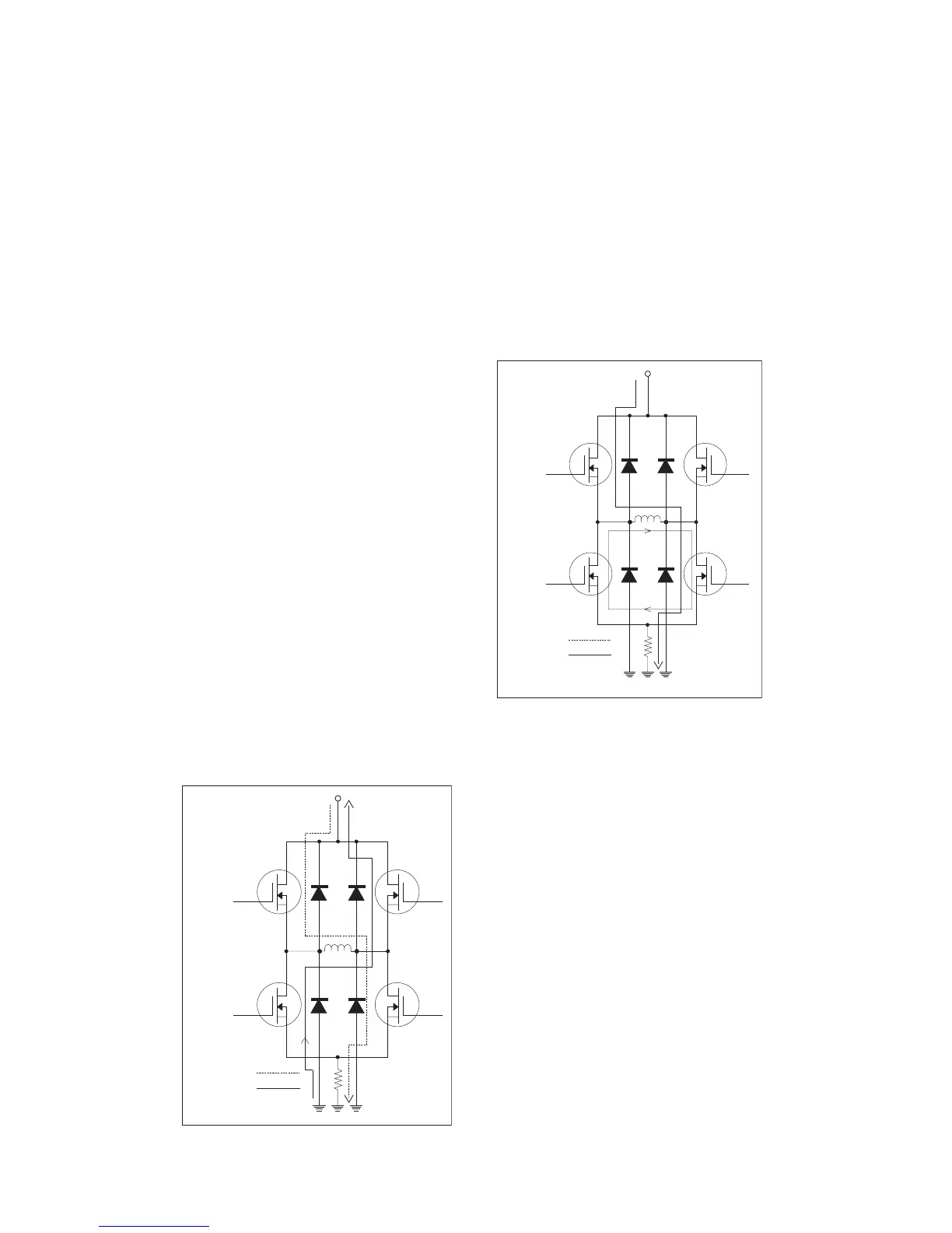
N o n - R e c i r c u l a t i n g
In a non-recirculating PWM,
the current ows up through
the bridge and back to the
supply in the OFF phase of
the cycle. This method of
controlling current allows for
much better response but re-
duces efciency and increas-
es current ripple, especially in lower
inductance motors (See Figure 4.3).
The IM2000’s PWM utilizes the best
features of both by combining recircu-
lating and non-recirculating current
control. On the rising edge of the
sine/cosine waveform, the PWM will
always be in a recirculating mode.
This mode allows the driver to run
at peak efciency while maintaining
minimum current ripple even with low
inductance motors. On the downward
cycle of the sine/cosine waveform,
the PWM operates in a two part cycle.
In the rst part of its cycle, the PWM
is in a non-recirculating mode to pull
current from the motor windings. In
the second part of the cycle the PWM
Figure 4.3: Non-Recirculating PWM