S e c t i o n 4
T h e o r y o f O p e r a t i o n
S e c t i o n O v e r v i e w
This section will cover the circuit operation for the IM483 microstepping
driver.
n Circuit Operation.
n Microstep Select Inputs.
n Stepping.
n Dual PWM Circuit.
n Fullstep Output.
n Timing.
C i r c u i t O p e r a t i o n
Microstepping drives have a much higher degree of suitability for ap-
plications that require smooth operation and accurate positioning at low
speeds than do half/fullstep drivers and reduction gearing. The IM483,
which can to be set to microstep resolutions as high as 51,200 microsteps/
rev (256 microsteps/step) using a 1.8° stepping motor, is ideal for such
applications.
In order to subdivide motor steps into microsteps while maintaining
positional accuracy, precise current control is required. The IM483 ac-
complishes this by the use of a unique Dual PWM circuit built into the
patented IM2000 Microstep Controller ASIC, which resides at the heart of
the IM483. This PWM circuit uses alternating recirculating/non-recircu-
lating modes to accurately regulate the current in the windings of a two
phase stepping motor.
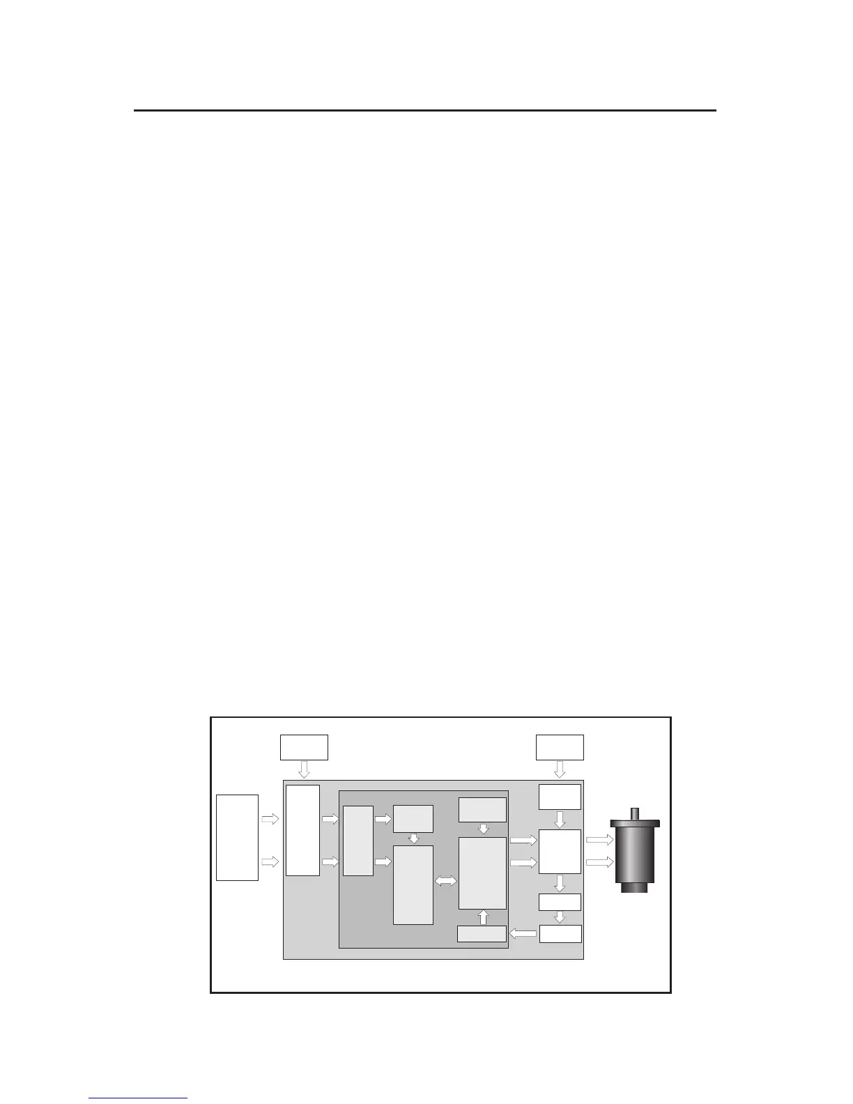
Figure 4.1: IM483 Block Diagram