EasyManua.ls Logo

IMS IM483 - Figure B.1 IM483-DC Connection

IMS IM483
83 pages
Print Icon
To Next Page IconTo Next Page
To Previous Page IconTo Previous Page
Loading...
66 IM483 Operating Instructions Revision R032306
67IM483 Operating Instructions Revision R032306
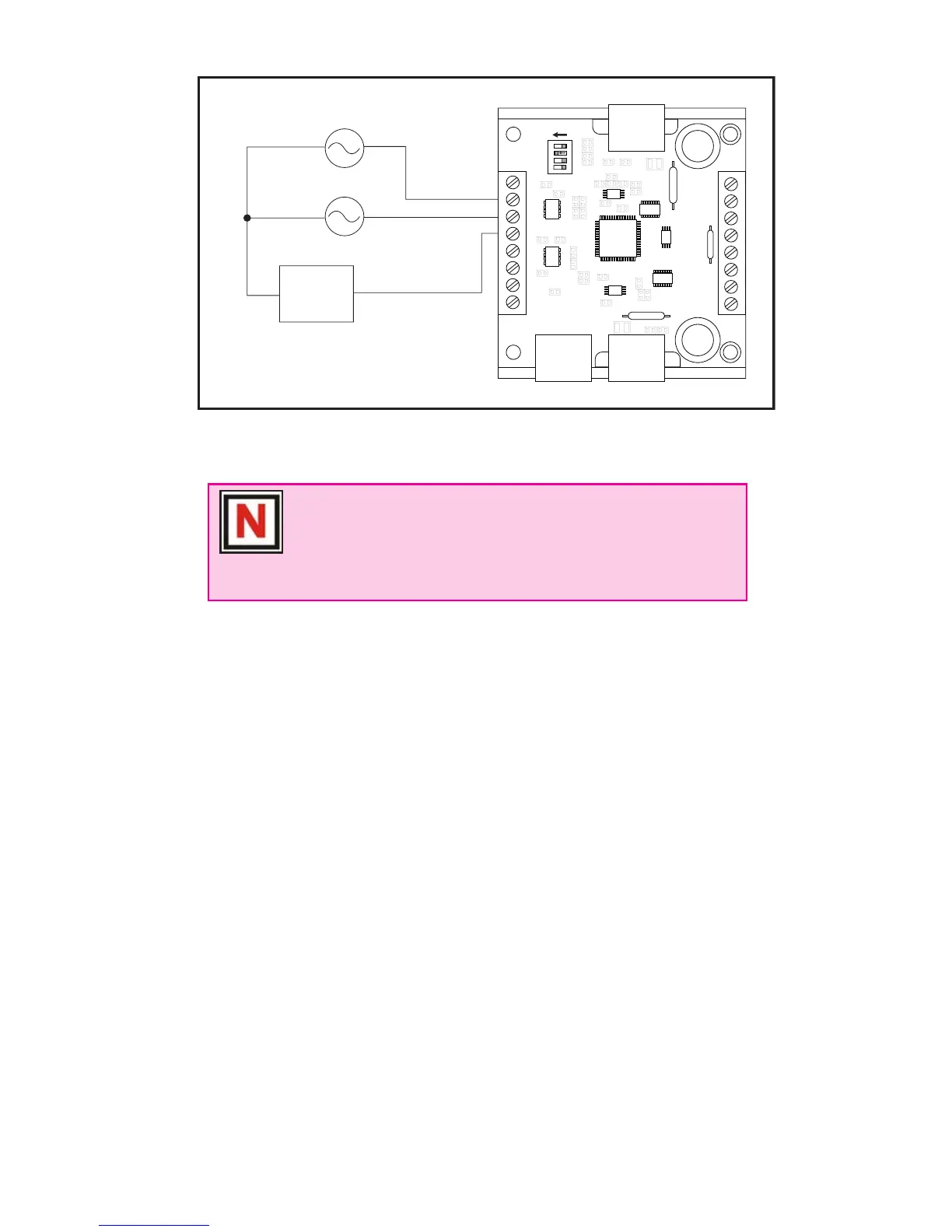
Figure B.1: IM483-DC Connection
NOTE: The physical direction of the motor with respect to the
direction input will depend upon the connection of the motor
windings. To switch the direction of the motor with respect to
the CW and CCW step clock inputs, switch the wires on either
Phase A or Phase B outputs.
+5 VDC
Opto
Supply
Step Clock
Oscillator #1
Step Clock
Oscillator #2
CW P1:2
CCW P1:3
P1:1






 
P1:4
+

Table of Contents

Other manuals for IMS IM483

Related product manuals