25IM483 Operating Instructions Revision R032306
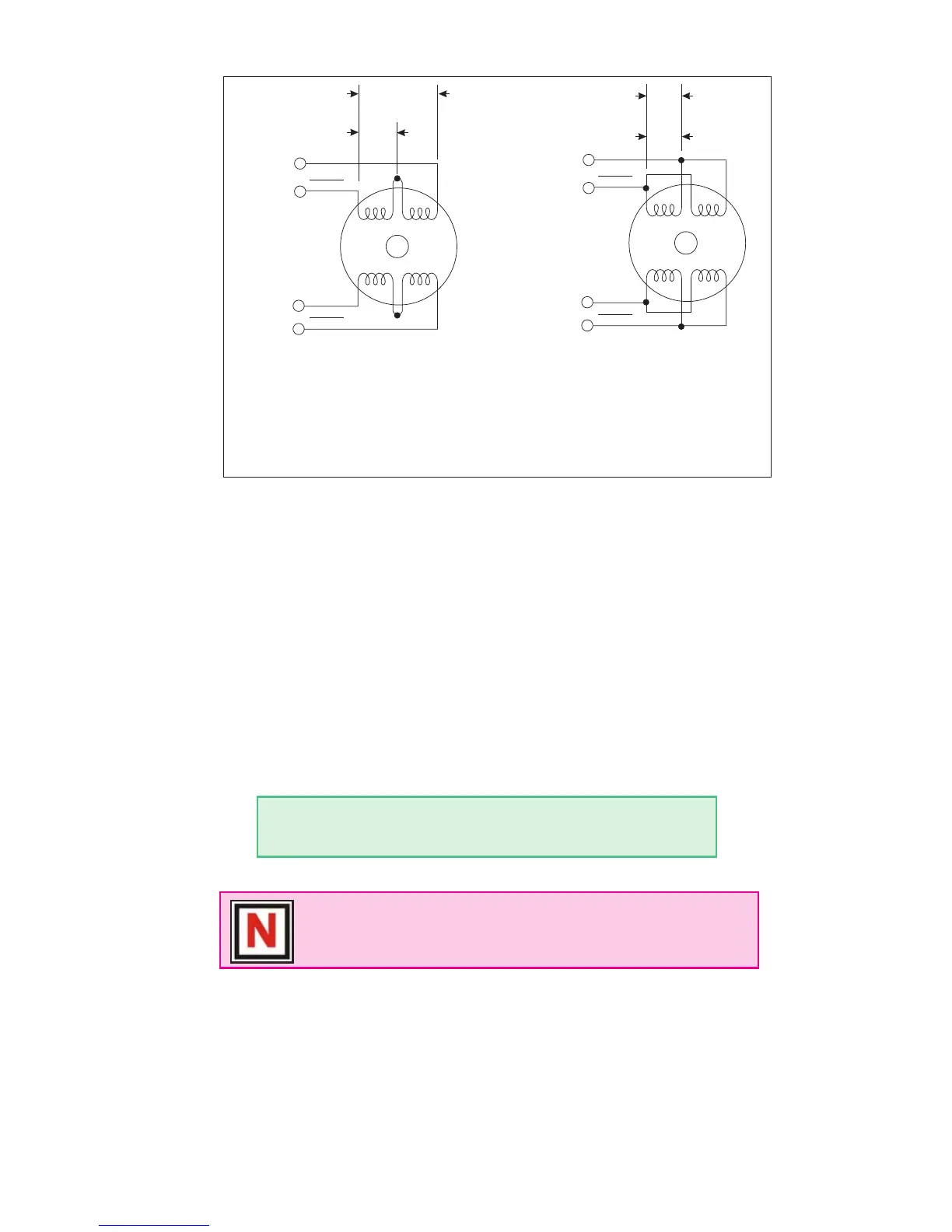
Figure 6.1 A & B: Per Phase Winding Inductance
The per phase winding inductance specied may be different than the
per phase inductance seen by your IM483 driver depending on the wiring
conguration used. Your calculations must allow for the actual inductance
that the driver will see based upon the wiring conguration.
Figure 6.1A shows a stepper motor in a series conguration. In this
conguration, the per phase inductance will be 4 times that specied.
For example: a stepping motor has a specied per phase inductance of
1.47mH. In this conguration the driver will see 5.88 mH per phase.
Figure 6.1B shows an 8 lead motor wired in parallel. Using this congu-
ration the per phase inductance seen by the driver will be as specied.
Using the following equation we will show an example of sizing a motor
for a IM483 used with an unregulated power supply with a minimum
voltage (+V) of 18 VDC:
.2 X 18 = 3.6 mH
The recommended per phase winding inductance we can use is 3.6 mH.
Maximum Motor Inductance (mH per Phase) =
.2 X Minimum Supply Voltage
NOTE: In calculating the maximum phase inductance, the
minimum supply output voltage should be used when using an
unregulated supply.
PHASE A
PHASE A
PHASE B
PHASE B
8 Lead Stepping Motor
Series Configuration
8 Lead Stepping Motor
Parallel Configuration
PHASE A
PHASE
A
PHASE B
PHASE
B
(Note: This example also
applies
to the 6 lead motor
full copper configuration
and
to 4 lead stepping motors)
(Note: This example also
applies to
the 6 lead motor
half copper configuration)
Specified Per Phase
Inductance
Specified Per Phase
Inductance
Actual Inductance
Seen By the Driver
Actual Inductance
Seen By the Driver
A B