48 Model 5525-6025-6625 Parts & Specifications Manual Part # 99904215
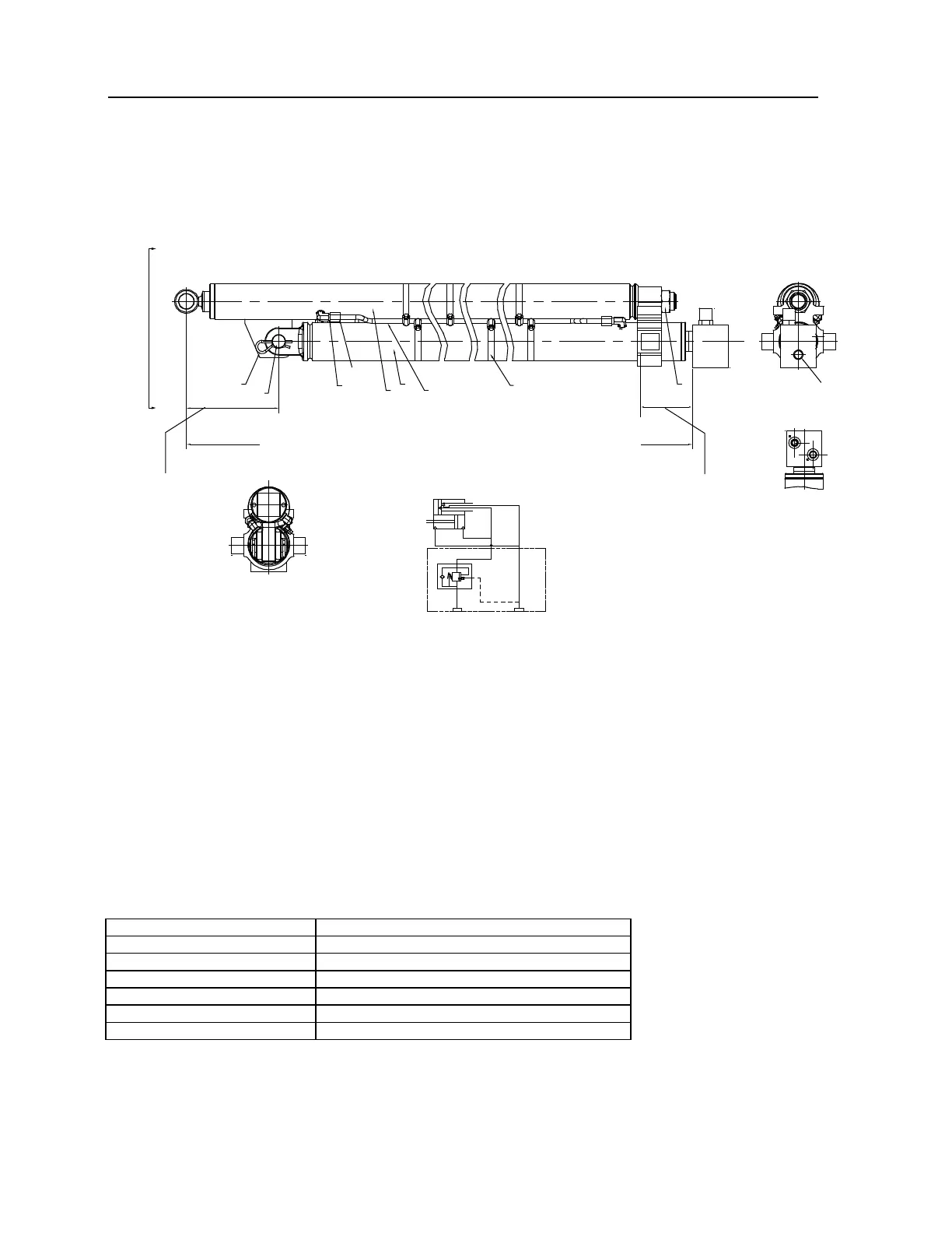
Cylinder Assembly, Extension (71410928) (Thru 4-07)
Reference Cylinder Assembly 71412666
8(2)
4
A
A
6(4)
5(4)
3
2
1
9(6)
7
C B A
D E F
ø0.75-10 UNC 2B
COUNERSUNK 0.75"
HYDRAULIC
SCHEMATIC
VIEW A-A
126.13" RETRACT - 276.13" EXTEND - 150" STROKE
VIEW B-B
7.75" RETRACT
85.75" EXTEND
4.38" RETRACT
82.38" EXTEND
NOTE:
1 REPLACE ALL COMPONENTS OF THE SEAL KIT WHENEVER THE CYLINDER IS DISASSEMBLED. THIS
WILL REDUCE FUTURE DOWNTIME.
2 APPLY REGULAR GRADE ANTI-SEIZE AND LUBRICATING COMPOUND TO THREADS ON CYLINDER
HEAD ONLY. KEEP AWAY FROM ALL SEALS.
3 APPLY "LUBRIPLATE" NO. 630-2 MEDIUM-HEAVY, MULTI-PURPOSE LUBRICANT, TO ALL PISTON, HEAD
GLAND, AND HOLDING VALVE SEALS, NYLON LOCK RING, CAST IRON PISTON RINGS, AND ROD
STINGER THREADS.
4 TORQUE ITEM #7 (LOCKNUT) WITH THREADLOCKING COMPOUND TO 325-380 FT-LB. USE LOCTITE
GRADE 271 OR EQUIVALENT.
5 HOSE CLAMP LOCATIONS NOTED WITH LETTERS, IN VIEW B.
BACK HYD. LINE TO ITEM #3
BOTH HYD LINES TO ITEM #3
FRONT HYD LINE TO ITEM #2
BACK HYDRAULIC LINE TO ITEM #2
BOTH HYDRAULIC LINES TO ITEM #2
FRONT HYDRAULIC LINE TO ITEM #2
 Loading...


