14
2.4 Planning for Installation and Programming, Required Field Documentation
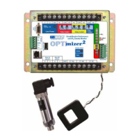
The OPTImizer
2
application should be planned, much like the application of other IEDs, such as a protective relay, fault
recorder, or monitor. Actual programming and installation can be accomplished in a few hours (typically 2 hours) after the
setpoints are calculated and determined. The required information is tabulated below:
Information Source(s)
AffecTed SeTTINgS / USe
CT Primary Coil Ratio
One Line Diagram, Visual Inspection of
Applied CT Ratio
• Bushing CT Ratio
Logic and Assertion Levels of
Aux A and Aux B inputs
Circuit Breaker Elementary Diagram
• Input Mode
• A Input Polarity
• B Input Polarity
Time Difference Between Aux
A input Assertion and Parting
of Main Contacts
Trip Trace, ANSI Standards (C37.06)
•A Input Delay
(Time Difference between Aux A input and
the main contacts parting)
Breaker Nameplate Data
Breaker Manufacturer’s Data Sheets,
Breaker Nameplate, ANSI Standards
(C37.06)
• Contact Life Mode
(I
2
x T or I x T)
• Contact Life Danger Limit
• Contact Life Warning Limit (%)
• Operations Count Limit
• SF
6
Gas Fill Weight
• SF
6
Gas Fill Pressure
• SF
6
Gas Fill Temperature
• Breaker Volume
Breaker Trip History
Operations Logs, Relay Fault Records,
Digital Fault Recorders, Oscillographs,
Estimation
• Preset Remaining Contact Life
(% for each phase)
Type of Breaker for employing
Restrike Detection
Generally used on SF
6
Gas Breakers • Restrike Alarm (Enable / Disable)
System Frequency • Power System Frequency
Date • DATE
Time • TIME
Site Identication System Topology, Mapping • Site Name
Baud Rate, Parity, Flow
Control, Stop Bits
Pre-programmed Setting, Interfaced
Communication Equipment if Networked
• Port Settings
Table 1: Required Information for Application