19
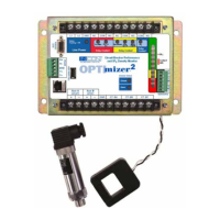
Interface to the Breaker Control Circuits
Two discrete voltage inputs are used to obtain information
to determine the start of the trip (Aux A) and the end of
mechanism travel (Aux B). These two inputs may be
directly coupled, using parallel wiring connections, to
the breaker control circuit or separately wetted breaker
auxiliary contacts. Additionally, auxiliary relays or diodes
may be used for isolation or to accommodate dual trip
circuits. No shunts are required.
Depending on the application, the voltage state can
change from no-voltage to voltage, or voltage to no-
voltage. The OPTImizer² is programmed to react to one
of the changes as an assertion to an input. De-bounce
circuitry is employed, and input assertions are dened as
the rst transition point in voltage.
Aux A Input Interface
The Aux A input is the starting trigger for the Trip Time log
and the mechanism time log. With the time adjustment
from the A INPUT DELAY setting, the Aux A starts the arc
duration log and the wear duty logs.
The Aux A input interface is made using a parallel connection
in the actual breaker control circuit: to the trip initiate
(shunting of the red light or the Trip Coil); to the 52 / a
contact (closed to opened), or an individually wetted 52 / a
contact (closed to opened) that is not in the actual trip circuit.
There are other possibilities using additional interface
devices, such as isolating relays and diodes.
There are advantages to using the Trip Coil signal for
assertion of the Aux A input:
• Allows capture of the latch time in the Trip Time log.
As many mechanism problems are in the latch, this
is the most important advantage. Use of the 52 / a
contact for interface will not allow capture of the
latch time in the mechanism time log.
• Repeatable signal with no “slop” issues as can occur
with mechanically linked auxiliary contacts.
The OPTImizer²’s Aux A input is fused, optically isolated
and transient protected. If it fails, it will be open, therefore
it cannot cause a false trip or short circuit when applied in
actual breaker control circuits.
Aux B Input Interface
The Aux B input is the stopping trigger for the mechanism
time log. The Aux B input assertion can be made using
either a green light signal (off to on) or a 52 / b contact
state change (opened to closed). There are other
possibilities using additional interface, such as isolating
relays and diodes.
The Aux B input is fused, optically isolated and transient
protected. If it fails, it will be open, therefore it cannot
cause a false indication or short circuit when applied in
actual breaker control circuits.
INPUT MODE
The Aux Input logic mode can be programmed for one of
four conditions:
Mode 1: Use this mode when the Aux A & B Input voltages
remain continuously high or low until a breaker event
occurs (as when wired across the red and green lights),
then change to the opposite state and remain constant
until the breaker is reset. In this mode, TRIP TIME and
CLEARING TIME are not logged and their alarms are
disabled.
Mode 2: Use this mode when the Aux A Input voltage
changes state momentarily, when a breaker event occurs
(as when wired to the trip coil signal), but Aux B is not
wired. In this mode, TRAVEL TIME and CLOSING TIME ,
and A-B LOGIC data are not recorded and their alarms are
disabled. The circuit breaker OPEN and CLOSED states
cannot be indicated in this mode. The red “CLOSED” LED
will be lit continuously.
Mode 3: Use this mode when the Aux A Input voltage is
continuous, as in Mode 1, but Aux B is not wired . (Used
in cases where there is no Aux B switch available) In
this mode, TRIP TIME, CLEARING TIME, TRAVEL TIME,
CLOSING TIME, and A-B LOGIC data are not logged and
their alarms are disabled.
Mode 4: Use this mode when the Aux A Input voltage
changes state momentarily, when a breaker event occurs
(as when wired to the trip coil signal) and the Aux B input
voltage remains continuously high or low until a breaker
event occurs, then changes to the opposite state and
remains constant until the breaker is reset. In this mode,
the OPTImizer² can record TRIP TIME, CLEARING TIME,
TRAVEL TIME and A-B LOGIC data and their alarms can
be active. Closing Time cannot be recorded and its alarm
will be disabled.
TRIP TIME (Trip Mechanism Time Log) (Input Modes 2
& 4 only)
When INPUT MODE 2 or 4 is selected and the "Aux A"
input is wired as shown in Figure 14, the OPTImizer²
will record TRIP TIME. The TRIP TIME log consists of a
timer. The timer starts from an assertion of the “Aux A”
input, and stops with the de-assertion of the “Aux A” input,
adjusted by the A INPUT DELAY value. The assertion
level is dened in software (A INPUT POLARITY), and
is application-dependent. The TRIP TIME measurement
starts with the Trip Initiate voltage application to the Trip
Coil and ends when the 52a contact opens (+ / - A Input
Delay value), de-energizing the Trip Coil.