40
In summation, the OPTImizer
2
, when applied in parallel
with the green light, should be set as:
• B Input Polarity = “Positive”.
OPTImizer
2
Aux B
Input
+
+
52/b
Closed Open
B Input Polarity
= Negative
G
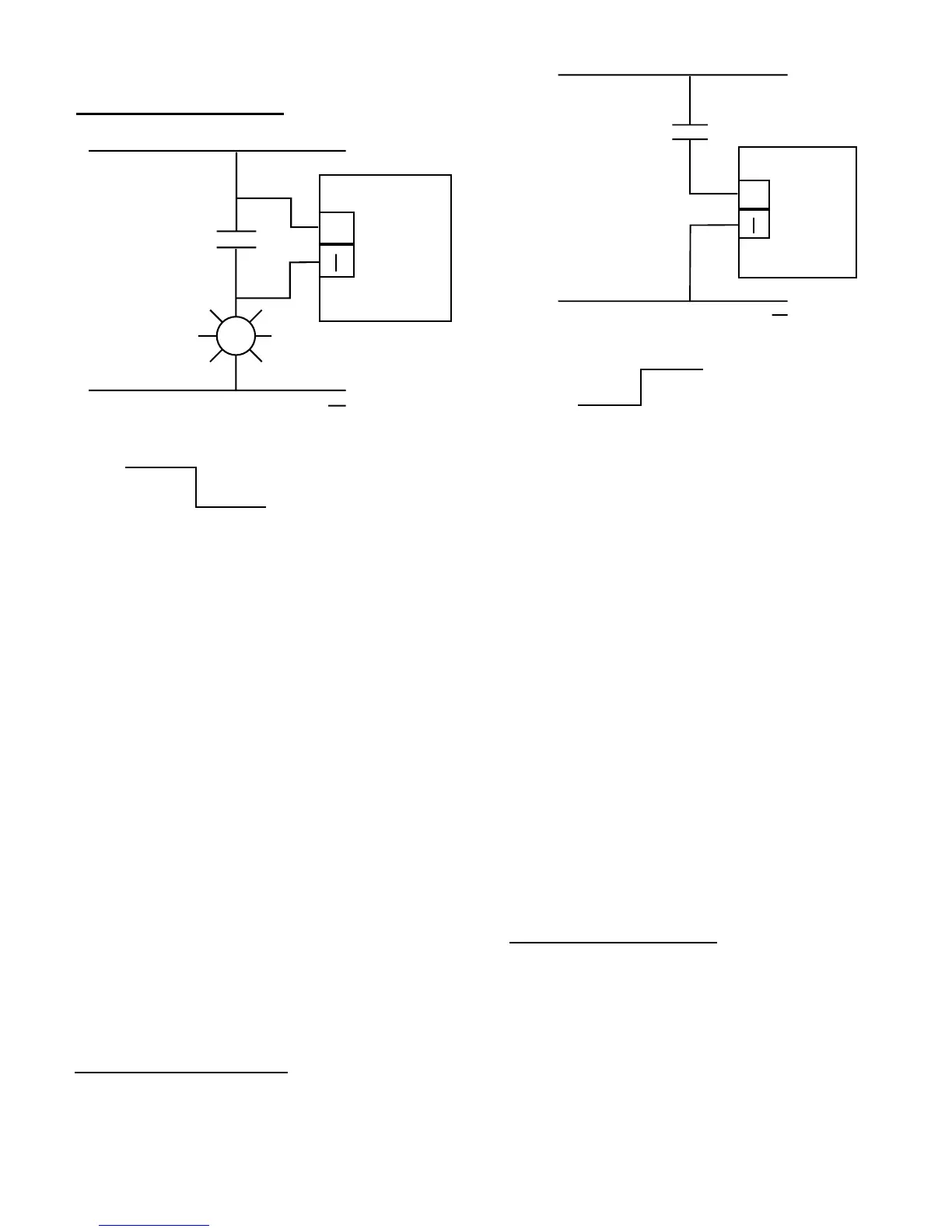
Figure 17: Aux B Interface, using 52 / b Contact in Green
Light Circuit
This is an elementary diagram of a typical 52 / b
contact / green light circuit. With the OPTImizer
2
Aux B
input wired in parallel with the 52 / b contact in the breaker
control circuit, the voltage levels sensed by the Aux B input
during a trip operation would be as follows:
• Breaker Closed - The 52 / b contact is opened. The
Aux B input would sense a voltage from the low
current circuit through the green light.
• Trip Command - One of the trip initiate contacts
closes. This causes high current to ow through the
trip coil, which begins to pull the latch. The Aux B
input would sense a voltage, with the 52 / b contact
remaining opened, as the breaker has not yet begun
to travel.
• Breaker Travel - As the breaker nears the end of
travel, the 52 / b contact closes. The Aux B input
would sense a transition from voltage to no-voltage,
as the voltage to the Aux B input is shunted.
• Fully Opened - The 52 / b contact remains closed,
and the Aux B input would continue to sense a no-
voltage condition.
In summation, the OPTI
mizer
2
, when applied in parallel
with the 52 / b contact, should be set as:
• B Input Polarity = “Negative”.
OPTImizer
2
Aux B
Input
+
+
52/b
Closed Open
B Input Polarity
= Positive
Figure 18: Aux B Interface, using Individually Wetted 52 / b
Contact
This is an elementary diagram of an individually wetted
SPARE 52 / b contact. With the OPTImizer
2
Aux B input
wired in series with this contact, the voltage levels sensed by
the Aux B input during a trip operation would be as follows:
• Breaker Closed - The 52 / b contact is opened. The
Aux B input would sense a no-voltage condition.
• Trip Command - One of the trip initiate contacts
closes. This causes high current to ow through the
trip coil, which begins to pull the latch. The Aux B
input would sense a no-voltage condition, with the
52 / b contact remaining opened, as the breaker has
not yet begun to travel.
• Breaker Travel - As the breaker nears the end of
travel, the 52 / b contact closes. The Aux B input
would sense a transition from no-voltage to voltage.
• Fully opened - The 52 / b contact remains closed,
and the Aux B input would continue to sense a
voltage.
In summation, the OPTI
mizer
2
, when applied to an
individually wetted contact, should be set as:
• B Input Polarity = “Positive”.