15
General Planning Considerations
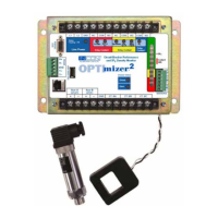
The OPTImizer
2
may be installed in a control house or breaker cabinet. The required interfaces can be obtained at either
location. The SF
6
sensors must be installed on the circuit breaker itself. Sensor accuracy is best when installed nearest to
the interrupter vessel.
The OPTImizer
2
should be installed as close to the CT Pickup Coils as possible. Cut any excess cable from the Pickup
Coils. It is not recommended to extend the Pickup Coil cables.
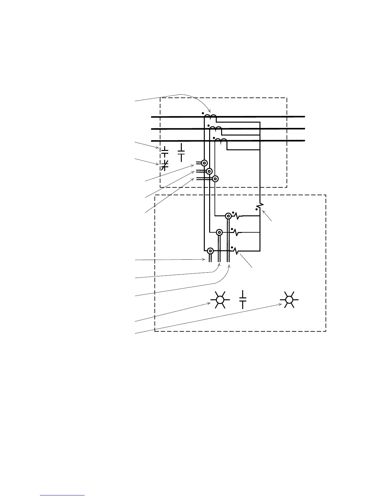
A
B
C
Aux B Interface
Aux A Interface
Phase A, Snap-on CT
Phase B, Snap-on CT
Phase C, Snap-on CT
Phase A, Snap-on CT
Phase B, Snap-on CT
Phase C, Snap-on CT
R
G
Aux A Interface
Aux B Interface
Bushing CT (Typ.)
Phase Relay (Typ.)
Ground Relay
(Typ.)
BREAKER CABINET
CONTROL HOUSE
or TI
TI
b
a
or
Figure 5: Breaker Cabinet and Control House Interface
Phase B, CT Pickup Coil
Phase B, CT Pickup Coil
Phase A, CT Pickup Coil
Phase A, CT Pickup Coil
Phase C, CT Pickup Coil
Phase C, CT Pickup Coil