61
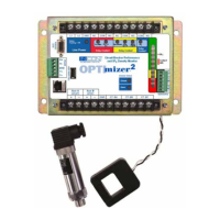
6 COMMUNICATION DETAILS
6.1 RS-232
The OPTImizer
2
uses asynchronous RS-232 communications. It is congured as a DCE device. A 9-pin
female connector is on the OPTImizer
2
for cable connection. The end of the cable that connects with
the OPTImizer
2
therefore is a 9-pin male.
(IN) DCD 1
(IN) RXD 2
(OUT) TXD 3
(OUT) DTR 4
GND 5
6
(OUT) RTS 7
(IN) CTS 8
9
DTE Device
STRAIGHT- THROUGH
1 DCD (OUT)
2 RXD (OUT)
3 TXD (IN)
4 DTR (IN)
5 GND
6 N/C
7 RTS (IN)
8 CTS (OUT)
9 N/C
DCE Device
OPTIMIZER
2
9
Pin
9
Pin
(IN) DCD 1
(IN) RXD 2
(OUT) TXD 3
(OUT) DTR 4
GND 5
6
(OUT) RTS 7
(IN) CTS 8
9
DTE Device
STRAIGHT- THROUGH
1 DCD (OUT)
2 RXD (OUT)
3 TXD (IN)
4 DTR (IN)
5 GND
6 N/C
7 RTS (IN)
8 CTS (OUT)
9 N/C
DCE Device
9
Pin
9
Pin
Pins 1 and 4
are connected
internally
(IN) DTR 4
(IN) TXD 3
(OUT) RXD 2
(OUT) DCD 1
GND 5
6
(OUT) CTS 8
(IN) RTS 7
9
“NULL MODEM”
CABLE
1 DCD (OUT)
2 RXD (OUT)
3 TXD (IN)
4 DTR (IN)
5 GND
6 N/C
7 RTS (IN)
8 CTS (OUT)
9 N/C
DCE DeviceDCE Device
Pins 1 and 4
are connected
internally
9
Pin
9
Pin
OPTImizer
2
Figure 25: 9-pin to 9-pin Cable Connections
Note: All references are to DTE 9-pin convention.