25
T
ref
=0
Current
"Aux A" input
"Aux B" input
30 40 50 60 70 80 9020
TIME (mS)
Not Asserted
Asserted
Pre- or Post Trip Event, Asserted
Pre- or Post Trip Event, Not Asserted
Aux A Input asserts at T
ref
= 0
Main Contacts open at T=24mS
Arc Extingushes at T=56mS
Arc Duration 56mS minus 24mS=32mS
Aux B Input asserts at T=94mS
Aux A assertion is 24mS earlier than Mains Parting
AD = +24
10
0
AD = +24
Total Arc Duration =
32mS
100
110
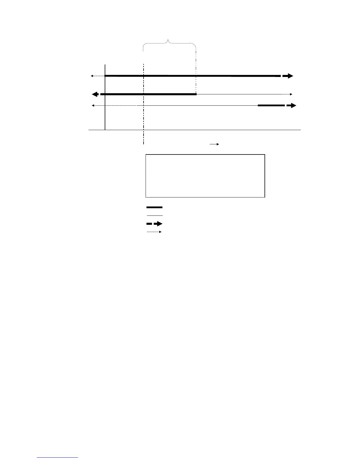
Figure 7: Trip Trace, Using Trip Initiate to Start OPTImizer
2
Example:
• The Aux A input on the OPTImizer
2
is asserted by the trip initiate signal (red light) in the breaker trip circuit
• The recorded TRAVEL TIME is 94ms
• The recorded ARC TIME is 32mS
• The A INPUT DELAY Setting is +24mS, as the assertion to the Aux A input on the OPTImizer
2
is the trip initiate
signal, which asserts 24mS before the main contacts part (A INPUT DELAY is positive when the assertion to the
Aux A input is earlier than the main contacts parting)
• The ARC TIME alarm limit is 48mS (32mS plus 16mS margin)
• The TRAVEL TIME alarm limit is 141mS (94mS plus 47mS margin)
This OPTImizer
2
would not be in an alarm state after this operation.
A Input Delay = +24
A Input Delay = +24