5
List of Figures
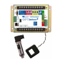
Figure 1: OPTImizer
2
Field Wiring ...................................................................................... 10
Figure 2: OPTImizer
2
Mounting Dimensions (Not actual size) ........................................... 11
Figure 3: OPTImizer
2
General Dimensions ......................................................................... 12
Figure 4: DSDP Sensor Connections ...................................................................................13
Figure 5: Breaker Cabinet and Control House Interface ...................................................... 15
Figure 6: Typical Trip Trace, with Arc Duration Information Superimposed .......................... 18
Figure 6A: Trip Trace, Using Trip Coil Voltage to Start OPTImizer
2
.................................... 22
Figure 6B: Event to Time Correlation of Fig 4, ..................................................................... 23
Figure 6C: Event to Time Correlation of Fig 4, ..................................................................... 24
Figure 7: Trip Trace, Using Trip Initiate to Start OPTImizer
2
............................................... 25
Figure 8: Alarm Relay Assignments ...................................................................................... 27
Figure 9: User Interface, Conguration Page ....................................................................... 33
Figure 10: User Interface, Conrming Conguration Update ................................................ 34
Figure 11: User Interface, Action Page ................................................................................. 34
Figure 12: Aux A Interface, using Trip Initiate (Red Light) .....................................................37
Figure 13: Aux A Interface, using 52 / a Contact in Trip Circuit .............................................38
Figure 14: Aux A Interface, using Trip Coil Excitation Voltage ............................................. 38
Figure 15: Aux A Interface using Individually Wetted 52 / a Contact ..................................... 39
Figure 16: Aux B Interface, using Green Light ...................................................................... 39
Figure 17: Aux B Interface, using 52 / b Contact in Green Light Circuit ................................ 40
Figure 18: Aux B Interface, using Individually Wetted 52 / b Contact ...................................40
Figure 19: Trip Trace illustrating A Input Delay Setting Considerations ................................41
Figure 20: Estimated Trip Latch Release Times based on Nameplate Breaker Voltage ...... 43
Figure 21: Estimated Arc Time based on Nameplate Breaker Voltage ................................. 44
Figure 22A: A 3-Cycle Arc, No Restrike ................................................................................48
Figure 22B, A 5½-Cycle Arc, No Restrike .............................................................................48
Figure 22C, A 5½-Cycle Arc, Restrike Detected ...................................................................48
Figure 23: User Interface, History Page ............................................................................... 54
Figure 24: User Interface, Status Page with Active Alarms .................................................. 60
Figure 25: 9-pin to 9-pin Cable Connections ........................................................................ 61
Figure 26: 25-pin to 9-pin Cable Connections ...................................................................... 62
Figure 27: Schweitzer Fiber-Optic Interface ......................................................................... 63
Figure 28: RS-485 Full-Duplex Wiring .................................................................................. 63
Figure 29: RS-485 Half-Duplex Wiring ................................................................................. 63
Figure 30: User Interface, Preferences Page ....................................................................... 64
Figure 31: User Interface, Editing the Preferences Page ..................................................... 64
Figure 32: User Interface, XML Page ................................................................................... 65
Figure 33: User Interface, XML Command Access ............................................................... 65