9
POWER INPUT
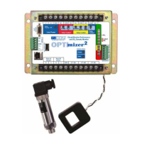
The OPTImizer
2
operates from station battery DC or from
AC station service power. Input Range: 110 to 250VDC, 90
to 264VAC. Power Consumption: 15 VA maximum.
COMMUNICATION PORTS
These ports are for setting, alarm acknowledgment, history
reset, and data viewing / dumping using the DNP3.0 protocol.
RS-232:
Connection: RS-232C, 9-pin female, DCE. A “straight
through” cable should be used for connection to a DTE
device, such as a PC. (Note: The ASCII protocol is no
longer supported on this port.)
Factory preprogrammed settings for RS-232 and RS-
485 communication:
Data bits: 8
Stop bits: 1
Parity: None
Baud rate: 9600 bps
Flow control: None
RS-485:
The port is full-duplex and un-terminated. The port can
be congured for half-duplex by adding jumpers from Tx+
to Rx+ and from Tx- to Rx-. If the OPTImizer² is the last
device in a network, the Transmit and Receive lines need
to be properly terminated with a 120 ohm resistor.
Ethernet:
This port is can be used with DNP 3.0 and TCP / IP
protocols simultaneously (in multi-sessions). When
connected to a secure local area network (LAN) the
OPTImizer² can be accessed remotely with a web browser,
providing the correct IP address is given. Firmware
upgrades can also be performed through this port using a
special upgrade tool (contact INCON Technical Services).
USB COMMUNICATION PORT
This port is for data dumping (BIN les and ASCII text
les), alarm acknowledgement or rmware upgrades. It
will Interface only to a USB memory stick. A memory stick
with a special software tool can be used to acknowledge
alarms. This software tool can be downloaded from the
OPTImizer
2
Product CD. A memory stick containing a
special upgrade script and les can be used to upgrade
the rmware (contact INCON Technical Services). (See
section 6)
COMMUNICATIONS SOFTWARE
The OPTImizer² is equipped as a web server. A common
web browser is all that is needed to communicate to the
OPTImizer² using the TCP / IP protocol. If DNP3.0 protocol
is used, the DNP Master device will have the proper
software for network communication. The OPTImizer²
will respond to properly addressed and validated DNP
commands.
DATA STORAGE
Data is stored in non-volatile memory. The memory holds
the most recent 5000 records in a database. A “record” will
be made of events that include: program settings changes,
CB opening, CB closing, alarm occurrences and scheduled
data logs.
SELF DIAGNOSTICS
A blinking green “power on” LED indicates satisfactory
operation of the microprocessor system. An "Input Signal"
LED indicates the malfunction of a CT Pickup Coil or
SF
6
sensor.
PHYSICAL
Size: 8.69W x 5.63H x 2.75D, Inches Nominal
Weight: 4 Lbs. 8 Oz.
PERFORMANCE
• Temperature: -20 to +150° F
• Surge Withstand: ANSI C37.90.1, SWC Test
• Electrostatic Dissipation: IEC 810-2
• Environmental: ANSI C37.1