User Guide - v7 13
After using the 2- way connector, ensure you tuck it under the cover to prevent it from
obscuring the field of view of the camera.
Binary IO connections
The camera has 2 opto-isolated binary inputs and 1 opto-isolated binary output. The table
below provides details of the binary IO connections on the 18-way IO connector.
Table 1: 18-way IO connector Binary IO connections
Signal Pin Number
IN1+ 5
IN1- 8
IN2+ 7
IN2- 10
OUT1A 4
OUT1B 6
The connector's pin numbering scheme is shown in Figure 7: on page 12.
Binary input
• Two opto-isolated binary inputs
• Maximum Input voltage 24V DC
• To set a Binary Input High, VIN should be 4V DC minimum, 24V DC maximum
• To set a Binary Input Low, VIN should be 1V DC maximum
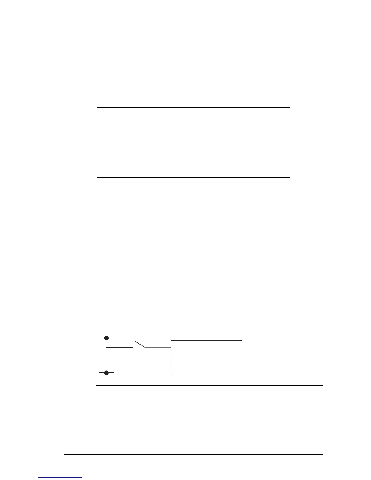
The binary inputs require an external voltage source to drive them. The voltage source is
normally connected via a controlled switch to a binary input. The positive connection from the
voltage source should be wired to the IN + pin (via switch), the negative connection to the IN -
pin.
When the camera is enabled via Control Center to generate binary IO events, connecting the
voltage source to an input triggers a rising edge binary IO event from the camera.
Disconnecting the voltage source from an input triggers a falling edge binary IO event from
the camera. The voltage source used should be between 4V and 24V DC. See Figure 9: on
page 13 for a simple example of a binary input connection.
Figure 9: Binary input connection
If voltage sources greater than 24V DC must be used then an external resistor is required.
The value of this resistor can be calculated as follows:
R = [ 100 * (VON - 1) - 1500 ] ohms rounded down to the nearest preferred resistor
value, where VON is the desired voltage for a logic high.
e.g. for VON = 48V DC
Enhanced SDFixed Dome - 9000 Range 2 Hardware Description