User Guide - v7 39
Connect the power supply to the heater via the terminal block inside the exit collar.
Connect the “+’ve” power supply wire to the heater assemblies Red/Blue wires, and the “-’ve”
power supply wire to the Black/Brown wires.
Fit the camera to the Exit Collar
When you have connected the camera, fit the Camera Assembly to the Exit Collar.
1. Ensure that the adhesive backed gasket is attached to the Exit Collar (9).
2. Connect the cables to the Camera Assembly (6) as required.
3. Connect the earth strap between the Exit Collar and the Camera Assembly using the
connection points provided.
4. Place the desiccant bag securely in the Exit Collar.
5. Fix the Camera Assembly to the Exit Collar by aligning the notch on the plastic base
plate with the key on the exit collar.
6. Secure the Camera Assembly to the Exit Collar using the three Security Screws (7)
and drive bit provided.
To ensure a watertight seal, tighten the security screws to a minimum of 15 Nm (11
lbs/ft) and maximum of 20 Nm (15 lbs/ft).
Setting up the sensor
When you are setting up the sensor, you can view analog video output on a video monitor.
This can be accessed by connecting the supplied analog video cable to the 2-way flying
connector within the camera.
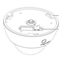
Figure 30: Camera lens assembly
Ensure the camera lens assembly does not obstruct the fan as this may reduce the
effectiveness of the fan, and impair image quality in low light conditions.
1. Remove the three security screws fixing the Bezel (1) to the Camera Assembly (6).
2. Remove the Bezel, the Dome Bubble (2) and the Lens Shroud (3).
3. Remove the safety label attached to the lens.
The sensor assembly may be hot. Hold the lens when positioning the camera lens assembly.
Enhanced SDFixed Dome - 9000 Range 4 Installation