User Guide - v7 29
1. Connect the required cables to the Camera Assembly (5).
2. Attach the base of the Camera Assembly to the Mounting Plate (6) so that the three
bayonet fixing points and interface connector area align correctly with the plate.
3. Rotate the Camera Assembly clockwise until it stops.
4. Secure the Camera Assembly to the Mounting Plate using the Securing Screw (4).
Setting up the sensor
When you are setting up the sensor, you can view analog video output on a video monitor.
This can be accessed by connecting the supplied analog video cable to the 2-way flying
connector within the camera.
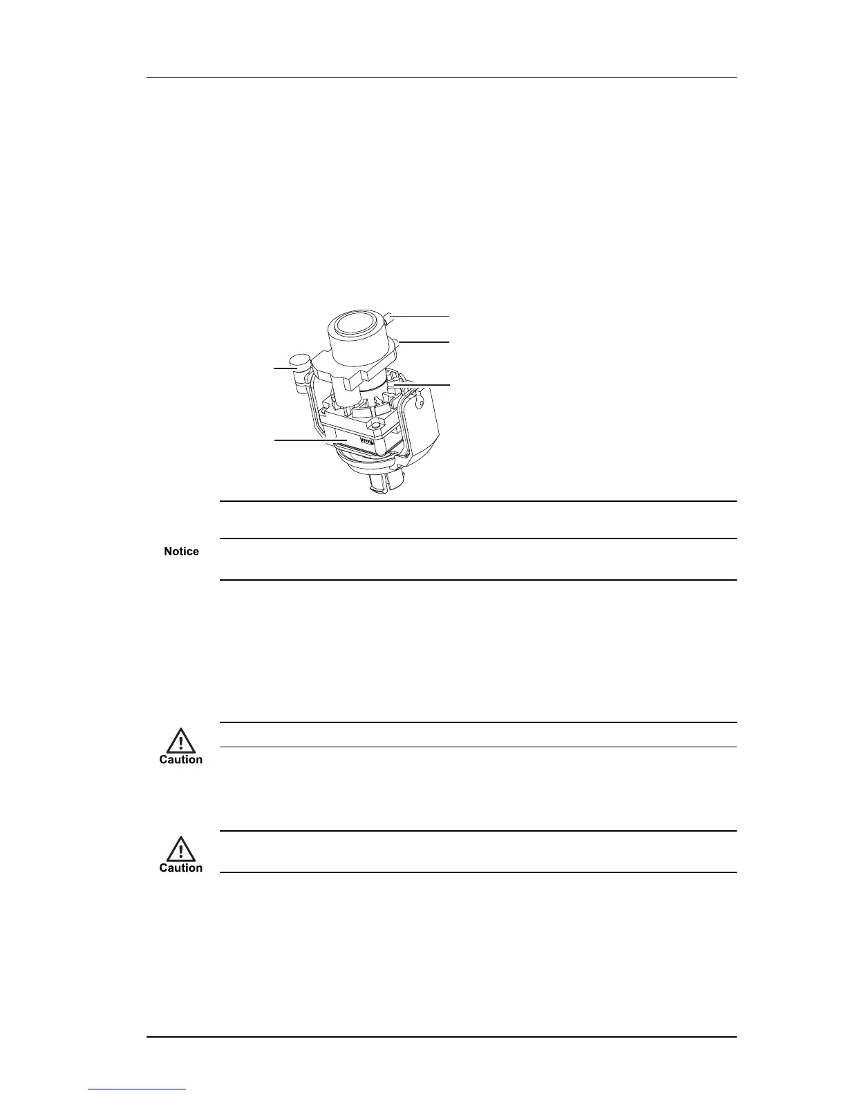
Figure 21: Camera lens assembly
Ensure the camera lens assembly does not obstruct the fan as this may reduce the
effectiveness of the fan, and impair image quality in low light conditions.
1. Remove the cover fixing screw (if fitted).
2. Rotate the Dome Bubble (1) anti-clockwise to release from the bayonet fixing on the
Camera Assembly (5).
3. Remove the Dome Bubble and the Lens Shroud (2).
4. Remove the safety label attached to the lens.
The sensor assembly may be hot. Hold the lens when positioning the camera lens assembly.
5. Release the locking screw and rotate the Lens Assembly (3) to the required position.
Secure the locking screw when done.
Take care not to over-rotate the camera lens assembly as this may result in the internal
cables becoming disconnected.
6. Focus the lens.
► For more information, see "Focus Procedure" on page 40
7. Re-fit the Dome Bubble and Lens Shroud. Take care to align the Dome Bubble so that
when rotated, the fixing screw hole aligns with the hole on the main Camera
Assembly.
Enhanced SDFixed Dome - 9000 Range 4 Installation