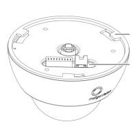
Figure 19: Mounting Plate dimensions
1. Use the profile template supplied with the camera to mark out the fixing holes and
cable access point on the mounting surface.
2. Prepare the holes and make the cutout on the mounting surface, fitting appropriate
mounting plugs.
3. Secure the Mounting Plate (6) to the surface using appropriate screws such as No.6 x
1inch (3.5mm thread by 25mm) pan head screws.
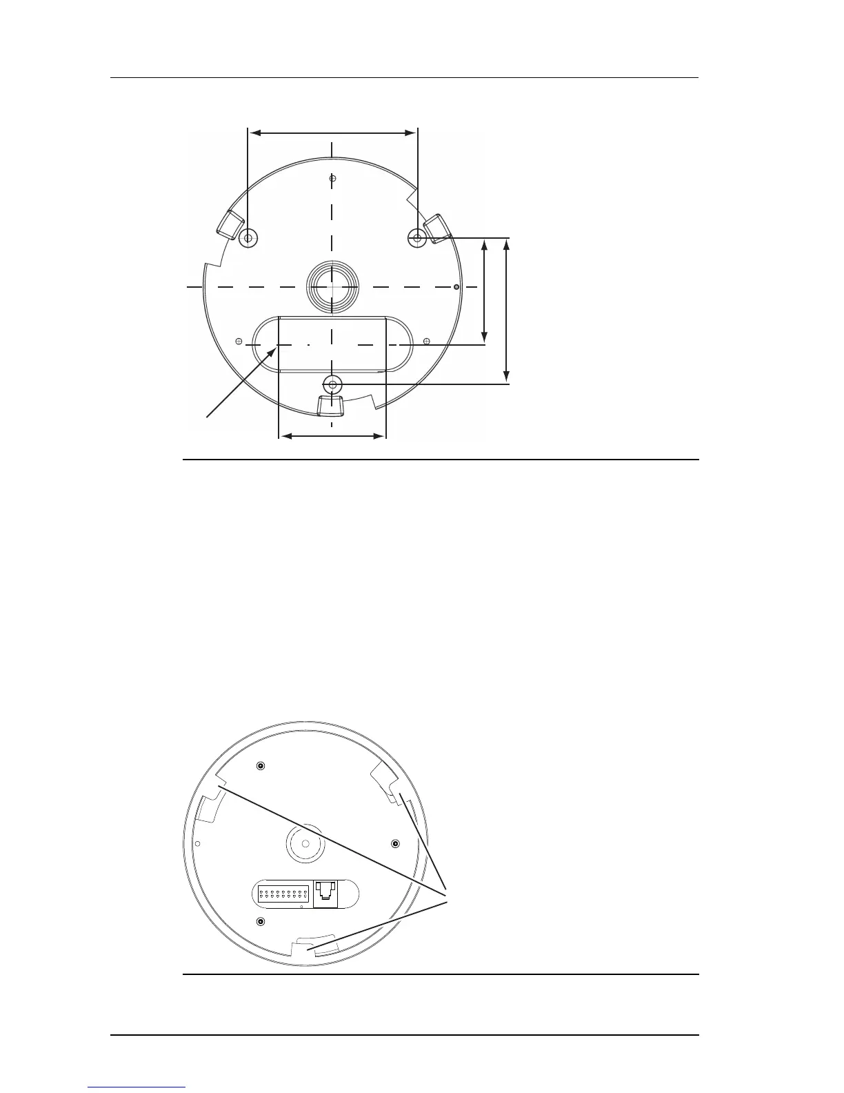
Run the cabling to the Mounting Plate
When the Mounting Plate has been fitted, run the required cables up to the access hole point.
Fit the Camera Assembly to the Mounting Plate